


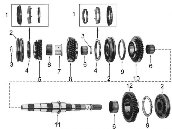
1 - synchronizer locking rings (late model years); 2 - assembly of the synchronizer; 3 - retaining ring; 4 - synchronizer locking rings (early model years); 5 - 3rd gear pinion; 6 - bearing; 7 - bearing sleeve; 8 - 2nd gear pinion; 9 - synchronizer locking ring; 10 - 1st gear pinion; 11 - driven shaft; 12 - reverse gear pinion
1. When performing points b) and e) of the driven shaft disassembly procedure, remember the installation positions of the 2/3 gear synchronizer locking ring assemblies.
 |
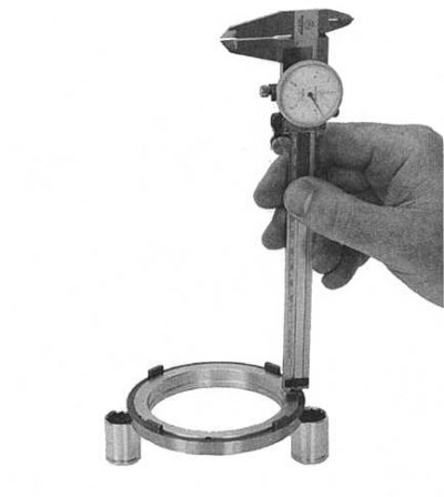 |
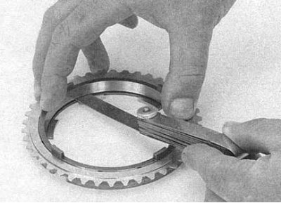
2. To check the serviceability of the 2nd and 3rd gear synchronizer locking ring assemblies, measure the gaps between the outer ring and the cone (see accompanying illustration), - its size should not exceed 0.2 mm and between the inner ring and the cone (see accompanying illustration), - the difference in heights should not exceed 0.2 mm.
3. When assembling the driven shaft components, install the 2nd and 3rd gear synchronizer rings in accordance with the instructions made during disassembly.
Note: On models produced since October 1994, the front input shaft bearing spacer sleeve and the intermediate shaft synchronizer cone washer have been removed.