Note. If the output shaft bearing has not been replaced, it must still be equipped with a new circlip.
2. Install the bearing holder on the carrier plate and tighten the bolts to the required torque.
3. Using a press, put the bearing on the input shaft (the outer race must be turned with a groove for the installation of the retaining ring away from the gear. Do not install the ring in the outer race at this stage. Transmission front components are shown in the accompanying illustration.
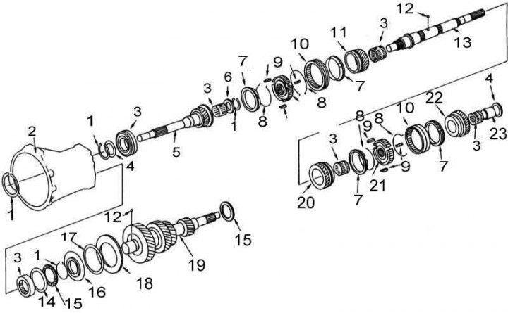
1 - retaining ring; 2 - clutch dome; 3 - bearing; 4 - washer; 5 - input shaft; 6 - distance ring; 7 - synchronizer blocking ring; 8 - spring; 9 - sliding keys; 10 - synchronizer clutch; 11 - driven gear of the 3rd gear; 12 - ball; 13 - driven shaft; 14 - adjusting washer; 15 - thrust bearing; 16 - bushing; 17 - conical spring; 18 - gear ring; 19 - intermediate shaft; 20 - driven gear 2nd gear; 21 - synchronizer hub; 22 - driven gear of the 1st gear; 23 - bearing clutch
4. Install the washer on the input shaft and measure the backlash between the retaining ring and the groove. Compare measurement result with regulatory requirements (see tables of sizes and adjustments at the end of the guide) and select a new retaining ring of the required thickness.
5. Lubricate the ball with a lithium-based multipurpose grease and install it in the countershaft. Install the gear ring, conical spring and bushing on the intermediate shaft. Make sure that the conical spring is turned with the concave side towards the gear.
6. Install the circlip on the intermediate shaft and tap it into place using a suitable size mandrel on the end of the shaft.
7. Using a brass drift and hammer, install the thrust bearing onto the intermediate shaft. Observe the bearing seating direction marked during disassembly.
8. Assemble the 1/2 and 3/4 synchro assemblies in the same order. Make sure that the ends of the springs are not caught on the same sliding keys.
9. Lubricate the 3rd gear roller bearing and slide it onto the driven shaft.
10. Install the 3/4 gear synchronizer assembly with blocking ring onto the 3rd gear. Slide the assembly onto the driven shaft using a press. Make sure that the hub and the synchronizer sleeve are turned with the tapered side forward.
11. Measure the backlash between the circlip and the groove. Compare the measurement result with the normative data (see tables of sizes and adjustments at the end of the guide) and select a new retaining ring of the required thickness.
12. Lubricate the 2nd gear roller bearing and install it on the opposite side of the driven shaft.
13. Install the 1/2 gear synchroniser assembly with locking ring onto the 2nd gear and slide the assembly onto the output shaft with a press, supporting the 2nd gear with the latter's support plates.
14. Put the first gear roller bearing clutch and washer on the driven shaft and seat the clutch with a press, supporting the washer with the plates of the latter. Remove the washer from the driven shaft.
15. Lubricate the first gear roller bearing and install the bearing/gear assembly onto the output shaft.
16. Lubricate the steel ball and washer with lithium based multipurpose grease and install them in the driven shaft.
17. If the components of the transmission housing, intermediate shaft, thrust bearing, toothed ring were replaced, or the intermediate shaft itself was replaced, check the axial play of the latter:
- Install the intermediate shaft in the bearing plate and put on the front end of the thrust bearing.
- Turn the clutch dome over and install the bearing plate with the intermediate shaft into it, achieving tight contact of the mating surfaces. Do not install countershaft front bearing shims at this time.
- Screw in and tighten the two fixing bolts.
- Fix the dial gauge on the bearing plate so that its plunger is pressed against the end of the intermediate shaft. Move the shaft up and down and read the instrument reading.
- Compare the measurement result with the standard end play values (see table below) to determine the required shim thickness:
| The value of axial play, mm | Required washer thickness, mm |
| 0.93÷1.02 | 0.88 |
| 1.03÷1.12 | 0.96 |
| 1.13÷1.22 | 1.04 |
| 1.23÷1.32 | 1.12 |
| 1.33÷1.42 | 1.28 |
| 1.43÷1.52 | 1.36 |
| 1.53÷1.62 | 1.44 |
18. If the extension housing, reverse idle gear, shaft or thrust washer has been replaced, check the reverse idle gear end play:
- Install the reverse idle gear thrust washer into the extension housing (as noted during the dismantling process).
- Slide the gear front thrust washer, roller bearings, and gear onto the reverse intermediate shaft and install the assembly into the extension housing, making sure the washer is seated in the correct direction.
- Attach the dial gauge to the extension housing by pressing its plunger against the end of the reverse intermediate shaft.
- Lay flatness gauge (edge of steel ruler) across the mating surface of the extension housing and press it against the end of the reverse intermediate shaft. Raise the shaft until it stops against the edge of the flatness meter and read the indicator reading. If the value of the axial play is out of range, it is necessary to select a new shaft rear thrust washer of the required thickness.
Note. Rear thrust washers are available in two sizes - 1.97 mm and 2.07 mm.
19. Clamp the carrier plate in a soft-jawed vise and lubricate the intermediate and driven shaft bearings with a lithium-based multipurpose grease.
20. Drive the rear end of the output shaft into the carrier plate by tapping the bearing holder with a soft-faced hammer. To be able to then install the intermediate shaft, do not plant the driven shaft to the end.
21. With grease, fit the 4th gear synchronizer block ring onto the 3/4 gear synchronizer hub and slide the assembly onto the driven shaft. Make sure that the grooves of the blocking ring are aligned with the sliding keys.
22. Lubricate the roller bearing and fit it together with the spacer into the input shaft. Put the input shaft on the driven one. While holding the input shaft, position the intermediate shaft so that the teeth of the spring ring are aligned with its teeth. This is necessary in order to engage the gears of both shafts. Install the intermediate shaft into the bearing plate, holding the upper bearing roller with a screwdriver to do this.
23. Completely seat the intermediate and driven shafts into the carrier plate by pushing the driven shaft while tapping the back of the plate with a soft-faced hammer.
24. Support the front end of the intermediate shaft and, using a suitable mandrel, seat the fifth gear roller bearing clutch on its rear end.
25. Using a mandrel, put the fifth gear on the driven shaft (just like it was installed before disassembly).
26. Install the carrier plate assembly with the shafts into the clutch dome.
27. Lubricate the roller bearing of the fifth gear and put it on the intermediate shaft.
28. Simultaneously install the reverse intermediate shaft and fifth gear. Make sure that the shaft mounting pin is in the recess.
29. Place the reverse gear cone on the intermediate shaft, and the reverse gear roller bearing clutch on the driven (use a suitable mandrel).
30. Install the reverse synchro ring assembly with sliding keys onto the fifth gear synchro clutch (how they were installed before disassembly). Install the assembly on the intermediate shaft, making sure that the coupling is turned with the beveled side away from the carrier plate. Install the 5th gear synchronizer ring.
31. Using a suitable mandrel, put the reverse gear on the intermediate shaft.
32. Install the front thrust washer of the reverse intermediate gear onto the gear shaft in the same direction as it had before disassembly.
33. Lubricate the output shaft reverse gear and reverse countershaft roller bearings and slide the components onto their shafts.
34. Fit your reverse idler thrust plate onto your shaft (how did she stand before disassembly).
35. Using a suitable mandrel, fit the reverse synchro hub and spacer onto the driven shaft. Make sure that the hub is turned with a notch towards the carrier plate.
36. Put the rear bearings on the intermediate shaft (use the mandrel).
37. Remove the carrier plate assembly with shafts from the clutch dome and clamp the plate in a soft vise.
38. Using a blade-type feeler gauge, measure the backlash between the C-rings and the groove in the output shaft. If the gap exceeds 0.1 mm, install new half rings of the required thickness.
39. Using a brass drift, install the half rings and holder, then seat the retaining ring.
40. Install the spacer ring on the rear end of the intermediate shaft and measure the backlash between the retaining ring and the groove. Compare measurement result with regulatory requirements (see tables of sizes and adjustments at the end of the guide) and select a new retaining ring of the required thickness.
41. Install the reverse coupling on the reverse hub, making sure that the coupling is turned with the beveled side towards the hub.
42. Using a blade-type feeler gauge, measure the end play of the 1st, 2nd, 3rd, and reverse gears of the driven shaft and the 5th gear of the countershaft. If the amount of play is out of tolerance (see tables of sizes and adjustments at the end of the guide), disassemble the transmission and carefully check the associated gears and related components for wear. Replace defective parts.
43. Install the fifth gear shift fork on the fifth gear synchronizer clutch. Slide the shift rod through the fork into the carrier plate. Insert a new roller pin.
44. Install the reverse shift fork on the reverse gear coupling, thread the shift rod through the fork into the carrier plate.
45. Install the 1/2 shift fork, locking shock lever and 3/4 shift fork as they were before disassembly and insert the shift rod.
46. Install a new roll pin in the impact lever and check the shift rod for smooth operation.
47. Install the reverse/fifth gear shift rod, lubricate the thread of the mounting bolt with a fixing sealant and tighten the latter with the required force.
48. Lubricate the intermediate shaft front bearing shim with lithium based multipurpose grease and install the washer in the clutch dome.
49. Lubricate with sealant 587 (or its equivalent) the mating surface of the clutch dome and install the carrier plate with the shafts, making sure that the mating surfaces fit snugly.
50. Install a new o-ring and test spring and ball into the retainer sleeve (lubricate the components with a lithium-based multipurpose grease). Install the coupling and tighten the fixing bolt to the required torque.
51. Lubricate the threads of the retainer plug with sealant and tighten the plug to the required torque.
52. Put a washer on the front end of the shift rod and install new circlips on the shift rod and input shaft bearing outer race.
53. Lubricate the lips of the new oil seal with lithium-based multipurpose grease and install the oil seal in the front cover.
54. Taking a new gasket, install the front cover on the clutch dome and screw in the mounting bolts (the threads of the lower three, located near the hole in the clutch release lever, must be lubricated with sealant).
55. Lubricate the lips of the new oil seal with lithium-based multipurpose grease and install the oil seal into the extension housing.
56. Lubricate with Loctite 587 (or its equivalent) mating surface of the carrier plate. Press the extension cover while guiding the selector bracket against the selector shaft. Make sure the mating surfaces are tight. Tighten the fixing screws to the required torque.
57. Using a punch, fit a new roll pin into the selector bracket.
58. Install the release lever and clutch release bearing.
59. Install the transmission on the car.