


2. Remove the clutch release lever and release bearing from the clutch housing (dome).
3. Unscrew the plug and remove the control spring and ball from the retainer sleeve located on the wall of the clutch dome (the components of the gearshift drive are shown in the accompanying illustration).
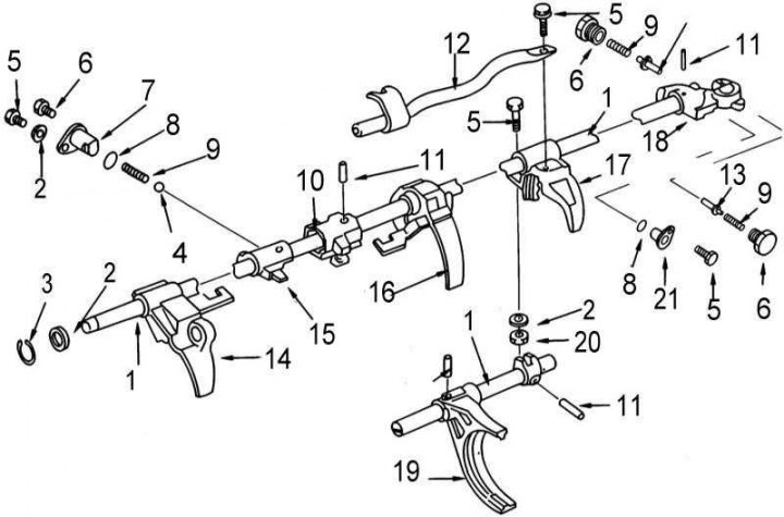
1 - shift rod; 2 - washer; 3 - retaining ring; 4 - ball; 5 - bolt; 6 - plug; 7 - retainer sleeve; 8 - sealing ring; 9 - spring; 10 - retainer; 11 - cylindrical pin; 12 - reverse/5th gear shift rod; 13 - plunger; 14 - 3/4 gear shift fork; 15 - impact lever; 16 - 1/2 gear shift fork; 17 - Reverse gear engagement fork; 18 - selector bracket; 19 - 5th gear engagement fork; 20 - nut; 21 - coupling
Loosen the mounting bolt and remove the retainer sleeve. Remove the sealing ring and discard it.
Note: If the control spring and ball are not removed early, they may fall into the transmission when the clutch is removed.
4. If not removed earlier, remove the spring and ball from the hole in the mating surface of the extension housing with the gear shift lever control housing.
5. Using a punch, knock out the cylindrical pin securing the selector bracket to the shift rod.
6. Loosen the mounting bolts and use a soft-faced hammer to remove the extension housing and selector bracket from the transmission. Remove the oil seal from the extension housing and discard it.
7. Loosen the mounting bolts and remove the top cover with the gasket, for which purpose insert the lever into the hole for installing the release lever in the clutch dome. Remove the seal from the cover and discard it.
8. Remove the retaining rings from the outer race of the input shaft bearing and from the shift rod. Remove the washer from the rod.
9. Support the rear of the driven shaft and use a soft-faced hammer to separate the clutch dome from the carrier plate. Remove the thrust bearing and adjusting washer from the front end of the intermediate shaft.
10. Clamp the carrier plate in a vice with soft jaws and loosen the bolt securing the reverse/fifth gear shift rod to the reverse gear fork. Remove the rod from the carrier plate.
11. Using a drift, knock out the cylindrical pin securing the striker and detent to the shift rod. Remove the shift rod from the carrier plate and remove the striker and detent, as well as the 1/2, 3/4 and reverse shift forks, noting the installation positions of the components.
12. Using a drift, remove the cylindrical pin securing the fifth gear fork to the shift rod. Remove the rod and fork.
13. Using a blade-type feeler gauge, measure the axial play of the first, second, third and reverse gears on the driven shaft. Also measure the axial play of the fifth gear on the intermediate shaft. If the axial play of any of the gears is outside the permissible limits (see size and adjustment tables at the end of the Manual), carefully check the relevant components for signs of wear, replace defective parts.
14. Remove the reverse gear coupling from the hub, remembering the installation direction of its fit. Remove the retaining ring from the end of the driven shaft, then use a hammer to remove the C-shaped retaining half rings (see illustration).
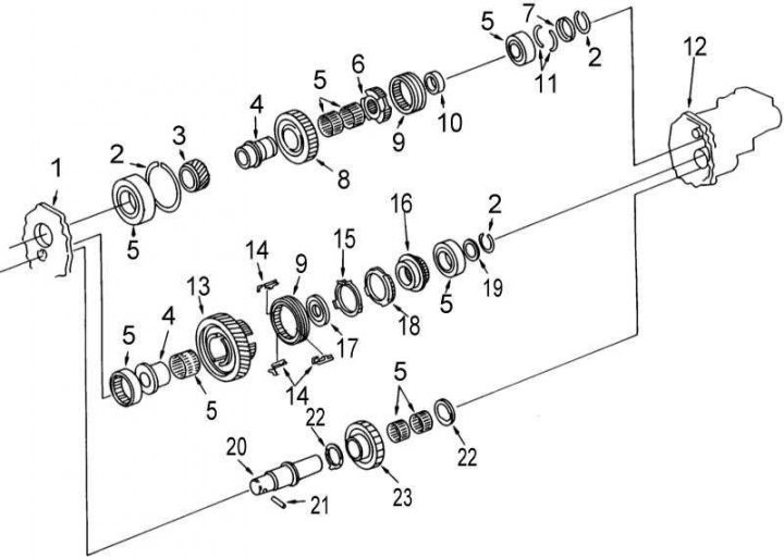
1 - carrier plate; 2 - retaining ring; 3 - driven gear of 5th gear; 4 - coupling; 5 - bearings; 6 - hub; 7 - holder; 8 - driven gear of the reverse gear; 9 - synchronizer clutch; 10 - spacer sleeve; 11 - C-shaped retaining half rings; 12 - extension casing; 13 - 5th gear drive pinion; 14 - Sliding key; 15 - blocking ring; 16 - Reverse gear drive pinion; 17 - reverse gear synchronizer cone; 18 - synchronizer locking ring; 19 - washer; 20 - intermediate shaft of the reverse gear; 21 - pin; 22 - thrust washer; 23 - intermediate gear of the reverse gear
15. Remove the snap ring and washer from the rear end of the intermediate shaft, then use a puller to remove the bearing and reverse gear.
16. Remove the gear, bearings and thrust washers from the intermediate shaft of the reverse gear, remembering the installation position of the latter.
17. Position the puller with the jaws behind the reverse gear pinion and remove the bearing, spacer sleeve, reverse gear hub, reverse gear pinion and roller bearings from the driven shaft. Try to remember the installation positions of the components.
18. Remove the fifth gear synchronizer sleeve with the locking rings and the fifth and reverse gear sliding keys. Try to remember the installation positions of the sleeve and sliding keys.
19. Using a puller, remove the reverse gear roller bearing sleeve from the driven shaft.
20. Position the puller with its jaws behind the fifth gear pinion and remove the reverse gear cone, fifth gear pinion and reverse gear intermediate shaft simultaneously.
21. Install the carrier plate in the press, supporting it with support plates and press the driven and intermediate shafts out of the plate one by one. Remember the position of the fifth gear of the driven shaft. After removing the intermediate shaft, extract the primary shaft and remove the roller bearings and spacer sleeve from the driven shaft.
22. Loosen the bolts and remove the bearing holder from the carrier plate.
23. Remove the washer, ball, first gear gear and roller bearing from the driven shaft.
24. Install the driven shaft in the press, supporting the second gear pinion with support plates and remove the first gear pinion roller bearing sleeve, the 1/2 gear synchronizer assembly and the second gear pinion with roller bearing.
25. Remove the snap ring from the front end of the driven shaft, then place the shaft in a press with the third gear pinion supported by support plates. Remove the 3/4 synchronizer assembly, third gear pinion and roller bearing.
26. Install the intermediate shaft in the press and remove the rear thrust bearing, remembering the installation direction of its fit. Remove the retaining ring from the front end of the intermediate shaft, then remove the bushing, conical spring, toothed ring and ball.
27. Remove the retaining ring and washer from the primary shaft. Install the primary shaft in a press, supporting the bearing with support plates and remove the latter.
28. Using a suitable drift, remove the bearings from the carrier plate, extension housing and clutch housing.
Text duplicated from the website: Nissanbook.ru
Gear Shift Lever Assembly Components
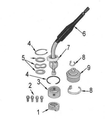
1 - spring; 2 - bolts; 3 - lower saddle; 4 - retaining ring; 5 - washers; 6 - gear shift lever; 7 - upper saddle; 8 - clamp; 9 - protective cover