


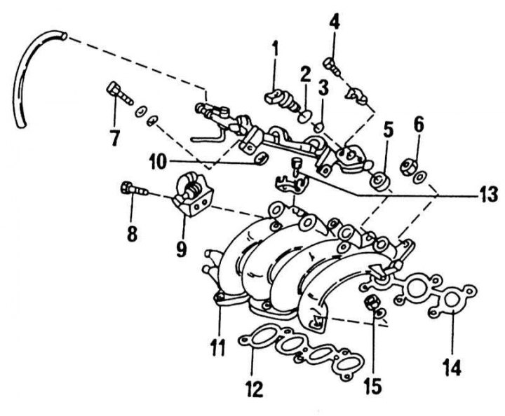
The upper part of the exhaust manifold and adjacent components on the SR20DE engine
1 - injection valve; 2 - O-ring seal, always replace; 3 - O-ring seal, always replace; 4 - bolt, 3-4 Nm; 5 - rubber gasket; 6 - nut, 18-21 Nm; 7 - bolt, 20-25 Nm; 8 - bolt, 18-22 Nm; 9 - throttle actuator drum; 10 - rubber gasket; 11 - upper part of the exhaust manifold; 12 - manifold gasket; 13 - bolt, 6-8 Nm; 14 - gasket; 15 - nut, 18-21 Nm
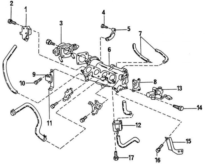
Lower part of the intake manifold and adjacent components
1 - intake manifold support; 2 - bolt, 16-21 Nm; 3 - throttle body; 4 - bolt, 16-21 Nm; 5 - intake manifold support; 6 - lower part of the intake manifold; 7 - vacuum hoses; 8 - gasket; 9 - transistor; 10 - bolt, 16-21 Nm; 11 - intake manifold support; 12 - air regulator; 13 - additional air valve; 14 - bolt, 6-8 Nm; 15 - intake manifold support; 16 - bolt, 16-21 Nm; 17 - bolt, 6-8 Nm
1. Before disassembling the engine, thoroughly clean all external surfaces to remove any dirt or oil. Pay particular attention to the sealing surfaces to ensure that no foreign objects can enter the engine when the sealing surfaces are separated. Secure the engine to a mounting stand. If there is no stand, place the engine on a workbench and support it with wooden blocks on the side so that it does not fall. The following description first describes the general disassembly process. Then, the individual design groups will be described separately.
2. If a manual transmission is installed, loosen the clutch bolts evenly in a cross pattern. Unscrew the bolts completely only after the tension in the clutch diaphragm spring has been released. Remove the clutch, take the driven disk out of the flywheel and put the parts aside. If the driven disk has a satisfactory appearance, do not touch it with dirty hands.
3. If an automatic transmission is installed, remove the torque converter. These operations are described in Chapter Automatic transmission.
4. Turn the engine over and remove the oil drain plug on the underside of the oil pan.
5. Unscrew the oil filter with a special key. If you don't have a special key, insert a powerful screwdriver into the filter from the side and, using its handle as a lever, unscrew the filter. Throw the filter away immediately.
6. Disconnect the ignition cables and remove the distributor cap with cables (fold back the spring clips of the lid).
7. Turn the crankshaft until the piston of the 1st cylinder is in the TDC position at the end of the stroke. To do this, turn the crankshaft by plugging the spark plug hole of the 1st cylinder with your thumb (unscrew the spark plug). When the finger feels pressure and the mark on the crankshaft belt pulley is in the position shown in the illustration, i.e. opposite the "0" mark, the crankshaft position is correct.
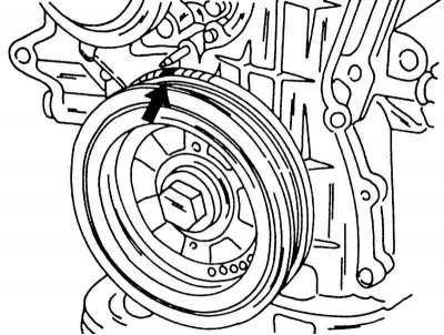
The piston of the 1st cylinder is in the TDC position if the "0" mark coincides with the pointer tip.
8. Using a scriber, draw a line on the outer edge of the ignition distributor opposite the tip of the runner. When installing, the distributor must be set in this position.
9. Loosen the distributor bolt and remove it.
10. Unscrew the remaining spark plugs.
11. Unscrew the fuel lines, vacuum lines and other additional components from the engine.
12. Unscrew the cylinder head cover and oil deflector.
13. Unscrew the exhaust manifold supports. The SR20DE engine has 4 supports, the SR20Di engine has one support.
14. Unscrew the intake manifold and adjacent parts. The SR20DE engine has a two-part intake manifold, which contains the parts shown in the illustrations The upper part of the exhaust manifold and adjacent components on the SR20DE engine and Lower part of the intake manifold and adjacent components parts. Unscrew the parts until both parts of the pipe can be separated and unscrew from the engine. Remove any loose gaskets. The SR20Di engine uses a single-piece intake manifold. The throttle body is screwed onto the intake manifold and can be pre-unscrewed. There are various parts located near the pipe that can also be unscrewed.
15. On the other side of the engine, unscrew the exhaust manifold cover and then remove the manifold. On this side of the engine, also remove the generator hanger bracket, the generator drive belt tensioner bracket, and the compressor console (if installed), cooling system outlet housing and oil dipstick.
16. On a carbureted engine, unscrew the intake manifold along with the carburettor and set it aside. Label the individual hoses connected to the carburettor before disconnecting them. The exhaust gas control valve and fuel pump are also on this side. Unscrew the exhaust manifold after removing the heat shield. Loosen and remove the three fittings screwed into the intake manifold. The lambda probe is also screwed into the manifold.
17. Remove the timing chain and camshafts as described in Section Cylinder head and timing drive. This operation also includes removing the crankshaft belt pulley.
18. The cylinder head is removed next. Since this job is similar to removing the timing chain, they are described together in Section Compression check. It should be noted already now that the cylinder head bolts must be of a certain length in order to be used again.
19. This should be remembered when removing and installing the cylinder head. Before performing the following work, the installation position of the pistons, connecting rods, bearings and bearing caps should be marked. The cylinder number can be scratched on the pistons (not too deep). Mark the connecting rods and bearing caps either with a center punch or lay out all the parts on the workbench so as not to mix them up.
20. Unscrew the oil pan. Turn the engine so that the pan is at the bottom. Oil sediment should not get inside the engine.
21. Unscrew the suction pipe screen. As you can see, the oil pan of the injection engine consists of two parts, but for disassembling the engine it can be removed as a single unit. In Section Engine lubrication system - general information a more detailed description of this work is given.
22. Clamp the hammer handle between the crankshaft and the crankcase wall and loosen the flywheel bolts one by one. Knock the flywheel down with a rubber mallet, making sure it does not fall. If an automatic transmission is installed, remove the torque converter drive disc in the same way.
23. Turn the crankshaft until all pistons are approximately halfway up and carefully scrape off any oil combustion products on the top side of the cylinders without damaging the bores.
24. Place a large container under the engine and collect the remaining oil and coolant in the block.
25. Unscrew the rear cover from the cylinder block and remove the gasket.
26. Unscrew the connecting rod bearing caps one by one. Lightly tap the cap with a rubber mallet and remove the cap together with the liners. Usually the caps and connecting rods are marked with numbers from 1 to 4, but it is necessary to check whether these markings are present.
27. Push the pistons with connecting rods out of the cylinders from below. To facilitate removal, two pistons should be in the BDC position. After this, immediately fasten the caps with liners on the corresponding connecting rods.
28. Remove the crankshaft. The crankshaft bearings differ for injection and carburetor engines. Removing the shaft is described in detail for both versions in Section Crankshaft and crankshaft bearings.