Table of contents: ECM relay ↓ Camshaft Position Sensor (number of…↓ Mass Air Flow Sensor (fault code 12) ↓ Ignition coil and key transistor…↓ Knock sensor (fault code 34) ↓ Throttle position sensor (fault code…↓ Speed sensor ↓ Nozzles ↓ Fuel pump ↓ IACV-AAC valve ↓ Recirculation valve ↓ EGRC-BPT valve ↓ Power steering oil pressure sensor ↓ Oxygen sensor (with heating) ↓ Adjusting the valve timing ↓ Fast Idle Cam ↓ Fan ↓
ECM relay
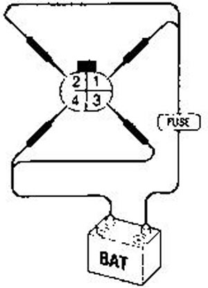
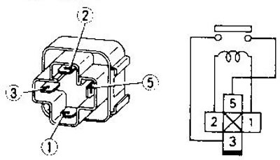
The relay is located under the engine control unit and is used to remove voltage from part of the ECM circuits by a signal from the unit itself. To test the relay, disconnect its connector and apply 12 V to contacts 1 and 2. Contacts 3 and 5 should close.
Camshaft Position Sensor (number of faults 11)
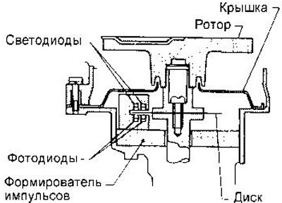
The sensor is a disk with 360 slots every 1° for the position signal and 4 slots for the reference signal every 180°. In GA engines for Europe, the disk does not have slots every 1° for the position signal. The disk slots pass through two optocouplers consisting of a light-emitting diode and a photodiode. Light pulses are converted by the photodiodes into voltage pulses and are fed to the ECM through a level-forming circuit.
When you receive a fault code #11, you must first perform the procedure to confirm it. Start the engine (crank the starter) for at least 2 seconds, then turn off the ignition for at least 7 seconds and turn it on again. Set the diagnostic mode II and get the fault code. If the fault is confirmed, check the sensor as follows (it is assumed that the wires and connectors, as well as the control unit, are in good condition):
1. Start the engine.
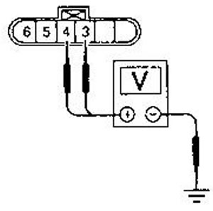
2. Check the voltage between ground and pins 3 and 4 on the AC voltage range. The voltage should be about 2.7 V (this is the average value for a pulse signal: the waveform can be seen with an oscilloscope). In GA engines for Europe the signal is only applied to pin 4.
3. Remove the distributor cap and visually inspect the disc for damage or contamination.
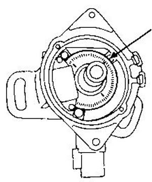
After troubleshooting, code #11 may still be displayed. Erase it from memory.
Mass Air Flow Sensor (fault code 12)
The mass air flow sensor (MAFS) is a thin wire located in a separate channel through which some of the air passes. The wire is heated by an electric current to a certain temperature. Since the cooling of the wire depends on the air flow, it is necessary to change the current through the wire to maintain a constant temperature. A signal proportional to the current through the wire; is fed to the ECM.
To confirm fault code #12, turn on the ignition, then after at least 6 seconds, start the engine and wait at least 3 seconds. Turn off the ignition and turn it on again after at least 7 seconds. Set the diagnostic mode 11 and get the fault code.
The sensor is checked as follows: (it is assumed that the wires and connectors, as well as the control unit, are in good condition):
1. Turn on the ignition.
2. Start and warm up the engine.
3. Check the voltage between contact 1 and ground. At idle with the engine sufficiently warmed up, the voltage should be within 1.2-1.8 V. With the engine stopped and the ignition on, the voltage should be less than 1.0 V.
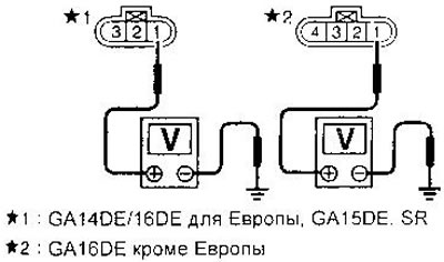
4. If the voltage is not within the specified limits, remove the sensor and check the condition of the wire. It should not be damaged or dirty.
Coolant temperature sensor (fault code 13)
The Engine Coolant Temperature Sensor (ECTS) is a thermistor whose resistance depends on temperature. Power is supplied to the resistor from the ECM.
To confirm fault code #13, turn on the ignition, wait at least 5 seconds, turn off the ignition for at least 5 seconds and turn it on again. Set the diagnostic mode II and get the fault code.
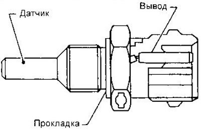
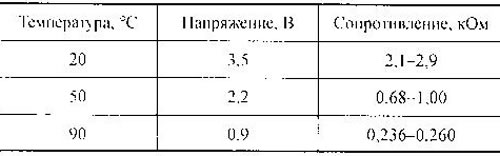
To check the resistance of the thermistor, unscrew the sensor and lower it into a heated bath of water:
Ignition coil and key transistor (fault code 21)
The ignition coil is built into the distributor. The signal from the ECM controls the key transistor, through which a current pulse is sent to the primary winding. At the same time, a high voltage is induced in the secondary winding.
If fault codes 11 and 21 are received simultaneously, first eliminate the cause that caused code 11.
To confirm fault code #21, turn on the ignition, turn off the engine (if it does not start, keep the key in the START position for at least 5 seconds), turn off the ignition, wait at least 7 seconds and turn it on again. Set the diagnostic mode II and get the fault code.
To check the ignition coil, disconnect its connector (two-pin, on the side of the distributor) and measure the resistance between the contacts. Contacts 7 and 8 are the terminals of the primary winding, the resistance between them at 25°C should be about 1 Ohm (0.5-1.0 Ohm for SR motor).
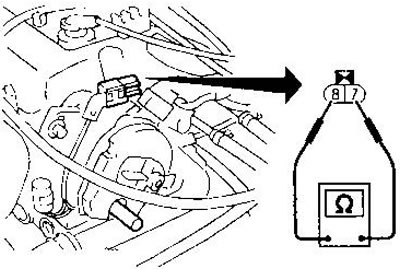
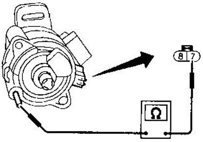
To check the secondary winding, remove the distributor cap. The secondary winding terminal is a metal pin. The resistance between it and contact 7 should be about 10 kOhm at 25°C for GA engines and 25 kOhm for SR engines.
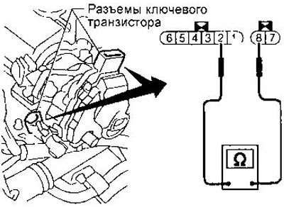
To check the key transistor, disconnect its connector (on the side of the distributor) and measure the resistance between contacts 2 and 8. If it is not equal to 0, the transistor is working properly. Bullet resistance, you say) transistor breakdown. The distributor must be replaced. (The figure shows the location of the connectors for GA motors).
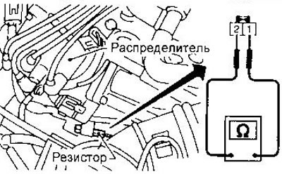
To check the resistor, disconnect its connector and measure the resistance between contacts 1 and 2. The resistance should be about 2.2 kOhm (at 25°C).
Knock sensor (fault code 34)
The knock sensor (KS) is attached to the cylinder block. It contains a piezoelectric element that reacts to the vibration of the cylinder block during detonation. When the piezoelectric is compressed, voltage is generated, which is fed to the ECM.
To confirm DTC 34, run the engine for at least 5 seconds. Turn the ignition off, wait at least 7 seconds, and turn it on again. Set the diagnostic mode to II and retrieve the DTC.
To check the sensor, you need an ohmmeter with a measurement limit of more than 10 MOhm. Disconnect the connector from the sensor and measure the resistance between contact 2 and ground. It should be within 500-620 kOhm,
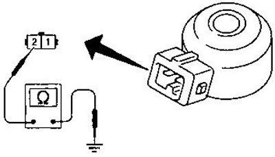
WARNING:
- Do not use a sensor that has been dropped or subjected to impact.
- Inlet air temperature sensor (fault code 41).
The inlet air temperature sensor (IATS) is mounted on the air cleaner housing. It is a thermistor, the voltage from which is supplied to the KSM. This sensor is not used directly for engine control, but is intended only for on-board diagnostics.
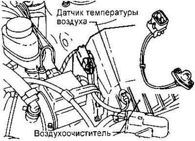
To confirm DTC #41, turn on the ignition and check the coolant temperature. It should be no more than 90°C. For a more accurate determination of the temperature, measure the voltage at pin 51 of the ECM connector. It should be more than 1.2 V. If not, turn off the ignition and wait until the engine cools down. Then turn on the ignition for at least 5 seconds, turn it off, wait 3 seconds and turn it on again. Set the diagnostic mode II and get the DTC.
To check the resistance of the sensor, remove it and place it in a heated bath of water.
At a temperature of 20°C, the resistance between the connector contacts should be within 2.1-2.9 kOhm, and at a temperature of 50°C, within 0.68-1.0 kOhm.
Throttle position sensor (fault code 43 in SR engine) - checking and adjustment
The throttle position sensor is a variable resistor whose movable contact is connected to the throttle valve. The voltage from the movable contact, proportional to the opening angle of the valve, is supplied to the ECM. In addition, this sensor determines the opening or closing speed of the throttle valve.
To check the sensor, turn on the ignition and measure the voltage between terminals 20 and 21.29 (ground) of the ECM connector. The voltage should be about 0.35-0.65 V with the pedal fully released and increase linearly to about 4-4.5 V when it is pressed.
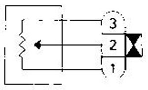
To check the sensor's variable resistor, disconnect its connector and measure the resistance between pins 2 and 3. With the throttle fully closed, it should be about 0.5 kOhm on GA engines (1 kOhm in SR motor), increase smoothly when the valve is opened and reach a maximum value of about 4.0 kOhm in GA engines (10 kOhm in SR motor).
Adjustments. With the accelerator pedal fully released, set the voltage at its output to 0.5 V by turning the sensor housing. After this, recalibrate. To do this, warm up the engine, turn off the ignition and no earlier than 5 seconds later disconnect the connector from the sensor. Then start the engine, wait at least 5 seconds (the gearbox must be in position N) and connect the sensor connector with the engine running.
Speed sensor
Vehicle speed sensor (VSS Vehicle Speed Sensor) is installed in the gearbox. It contains a pulse generator, the frequency of which is proportional to the speed of movement. The signal from the speed sensor is sent to the speedometer, and from it to the engine control unit.
To check the sensor, lift the front of the car and, while rotating the front wheel, measure the voltage at contact 32 ROM. 11 voltage should be in the range of 0-5 V (see also chapter "Electrical equipment", "Instrument cluster").**
Nozzles
The injector is a small precision electromagnetic valve with a spray nozzle that opens when the winding is shorted to ground via the ECM. The amount of fuel injected is determined by the duration of the control pulse.
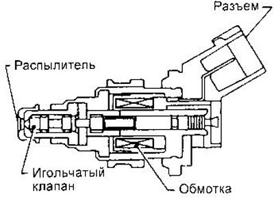
To check the injector on a running engine, place some tool against its body (for example, a screwdriver), the end of which you hold to your ear. The nozzle should make a clicking noise.
To check the electromagnet winding, disconnect the connector from the injector and measure the resistance between the terminals. It should be in the range of 10-14 Ohms (at 25°C).
Fuel pump
The fuel pump is switched on by the control unit immediately after the ignition is turned on to create the required fuel pressure. If the ECM does not receive a signal from the camshaft position sensor, the pump is switched off after 5 seconds, which avoids battery discharge and increases safety. After the engine is stopped, the pump is switched off within 1 second. The pump is controlled via a relay. The fuel pump relay is located under the instrument panel on the driver's side.
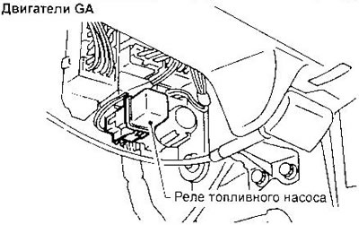
To check the pump operation, squeeze the hose that goes to the fuel filter in the engine compartment with your fingers and turn on the ignition. You should feel pressure pulsations for 5 seconds.
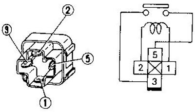
To check the relay, remove it and apply 12 V to contacts 1 and 2. In this case, contacts 3 and 5 should close.
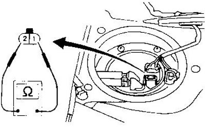
To check the pump itself, remove the inspection hatch under the rear seat, disconnect the pump connector and measure the resistance between contacts 1 and 2. It should be 0.2-5.0 Ohm (at 25°C).
IACV-AAC valve
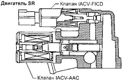
The Idle Air Control Valve (Idle Air Control Valve - Auxiliary Air Control) is designed to control the engine speed at idle. The optimum speed is stored in the ECM memory for different engine operating conditions (heating, engine braking, turning on the air conditioner, etc.).
The flow section of the valve changes according to the signal from the control unit. This changes the amount of air entering bypassing the throttle valve, and consequently the idle speed.
In addition to the IACV-AAC valve, the IACV-FICD valve is also installed (Fast Idle Control Device), designed to increase air supply when the air conditioner is turned on.
To check the IACV-AAC valve in GA engines (except Europe), disconnect the valve connector and measure the resistance between contacts 2 and 3, 3 and 4. It should be in the range of 50-100 Ohms (at 25°C).
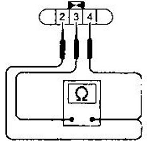
To check the IACV-AAC valve in GA engines for Europe, disconnect the valve connector and measure the resistance between its contacts. It should be about 10 ohms (at 25°C).
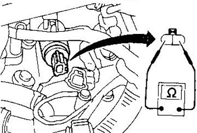
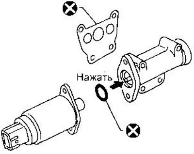
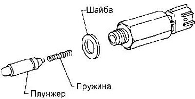
After removing the valve, check to see if the plunger is sticking. The O-ring and gasket should be replaced each time the valve is removed.
To check the operation of the IACV-FICD valve, start and warm up the engine, then measure the engine speed at idle. If it differs from normal, make adjustments (see the relevant section of this chapter). Then turn on the air conditioner. The speed should increase to 850-900 min⁻¹ or more, depending on the engine model.
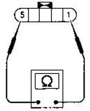
To check the IACV-FICD valve in GA engines (except Europe) disconnect its connector and measure the resistance between contacts 1 and 5. It should be in the range of 75-125 Ohm (at 25°C).
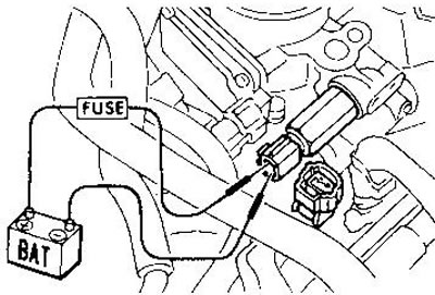
On GA engines for Europe and SR, disconnect the valve connector and apply battery voltage to it through the fuse gel. A clicking sound should be heard. If no clicking sound is heard, remove the valve and check for a sticking plunger or broken spring.
Evaporative Canister Purge Valve
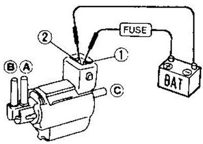
In GA engines, as well as in SR engines up to 04.96, this valve is also used to control the exhaust gas recirculation valve and is called the EGR and purge valve (EGR Valve and EVAP Canister Purge Control Solenoid Valve). When the electromagnet winding is shorted to ground via the ECM, the vacuum from the throttle pipe stops being supplied to the recirculation valve and the adsorber.
To check the valve, apply battery voltage to the service station connector through the fuse. This should open the channel between inputs A and C. B and close the channel between inputs A and C. In the SR engine for Europe from 04.96, input C is missing, so you only need to check the air flow between inputs A and B.
Recirculation valve
The recirculation valve (EGR - Exhaust Gas Recirculation valve) is used to supply part of the exhaust gases from the exhaust manifold to the intake manifold. The degree of opening of the valve is determined by the vacuum supplied to it. The vacuum is supplied through the recirculation and purge valve of the adsorber (see above).
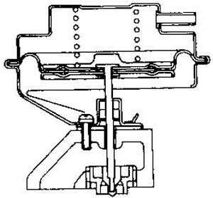
To test the valve, apply a vacuum to its input using a hand vacuum pump and check if the diaphragm rises.
EGRC-BPT valve
Used to change the vacuum supplied to the recirculation valve depending on the exhaust gas pressure.
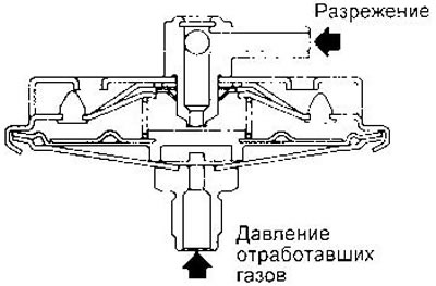
To check the valve, close one of its vacuum inputs, apply vacuum to the second and check for leaks when applying pressure up to 81 kPa to the lower input.
Power steering oil pressure sensor
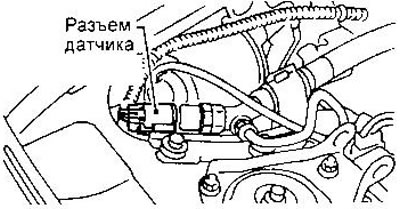
This sensor is connected to the high-pressure circuit of the power steering and is designed to determine the load on the power steering. When the steering wheel is turned, the pressure in the power steering increases, the sensor contacts close and the ECM increases the air flow through the IACV-AAC valve to increase idle speed and adapt the engine to the increased load.
When turning the steering wheel quickly, the voltage at pin 43 of the ECM connector should be about 0 V, in other cases - about 5 V (8-10V in SR up to 04.96).
Oxygen sensor (with heating)
The oxygen sensor is installed in the exhaust manifold. It determines the oxygen content in the exhaust gases in relation to the atmospheric air. The sensor's sensitive element is a zirconium ceramic tube. The tube's potential varies from approximately 1 V (lack of oxygen) to 0 V (excess oxygen). The optimal composition of the mixture corresponds to the point of a sharp change in potential.
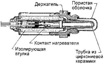
Checking the oxygen sensor is described in the section of this chapter devoted to checking and adjusting the idle speed.
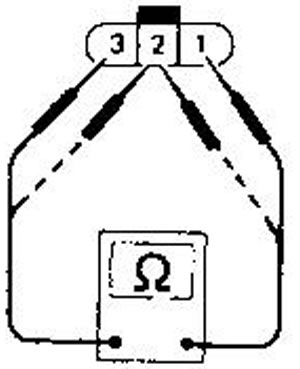
Yes, to check the gel heating, measure the resistance between contacts 1 and 3 of the sensor connector. It should be 2.3-4.3 Ohm at 25°C (3.3-6.3 Ohm in SR motor).
Adjusting the valve timing
The variable valve timing control (VTC) system is designed to change the opening and closing times of the intake valves depending on the current engine operating conditions.
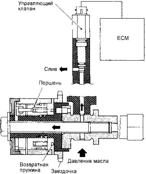
The position of the drive sprocket relative to the intake valve timing chain is controlled by the oil pressure, which is regulated by a valve controlled by the ECM.
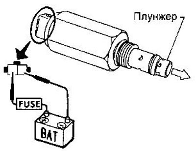
To test the valve, apply battery voltage to its connector through the fuse. The plunger should extend.
Fast Idle Cam
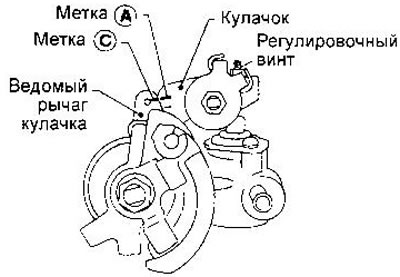
GA Engine for Europe. To check the operation of the fast idle cam, start the engine and warm it up to a coolant temperature of 80 = 5°C. To measure the temperature, disconnect the connector from the temperature sensor and connect an ohmmeter to it. The desired temperature is achieved when the sensor resistance is 0.26-0.39 kOhm. Check whether the A and C marks are aligned. If necessary, align the marks with the adjusting screw. The tightening torque of the screw is 0.98-1.96 Nm.
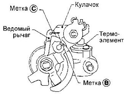
Stop the engine. Wait until the fluid temperature drops to 25±5°C (the sensor resistance should be 1.65-2.40 kOhm). Check the alignment of marks B and C. If they diverge, replace the heating element and repeat the above check and adjustment.
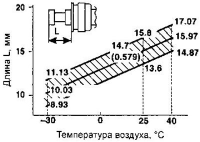
SR engine for Europe from 04.96. Remove the throttle body (see chapter "Engine", section "External components"). Keep the throttle body at ambient temperature for at least 3 hours to equalize the temperatures of the air and the heating element (wax filler).
Without removing the thermocouple from the throttle body, measure the length L. If it is within the shaded area, the thermocouple is OK. Adjust the cam as described below. Otherwise, replace the thermocouple.
Check the clearance A between the limiter and the throttle adjusting screw. If it is not within the shaded area, adjust with screw S. Do not turn the throttle adjusting screw.
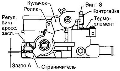
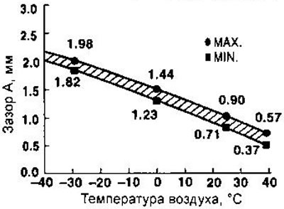
After adjusting the clearance A, tighten the lock nut of screw S.
Install the throttle body. Start and warm up the engine. Make sure there is clearance between the cam and the roller.
Fan
Models with manual transmission are equipped with single-speed fans, while models with automatic transmission are equipped with two-speed fans.
To test the fan relay, apply battery voltage through the fuse to contacts 1 and 2, then make sure contacts 3 and 5 are closed (single contact relay) or 3 and 5, 6 and 7 (relay with two groups of contacts).
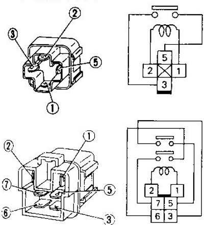
To test a single-speed fan, apply battery voltage to the contacts of its connector: "+" to contact 1, "-" to contact 2.
To test the two-speed fan on GA engines, apply battery voltage to the following terminals: "+" to terminal 1, "-" to terminal 4 (low speed); "+" to pin 2, "-" to pin 3 (high speed).
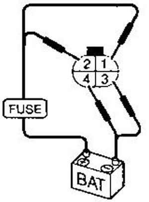
In SR motors, to turn on high fan speed, you need to apply "-" to contacts 1 and 2, "+" to contacts 3 and 4.