


Table of contents: Idle Air Control Valve (IAC) ↓ Fast Idle Speed Control Solenoid…↓ Fast Idle Cam ↓
Caution: When working in the engine compartment, try to keep hands, hair and clothing away from moving components such as drive belts, fan blades, etc.
Idle Air Control Valve (IAC)
When the engine is idling, the composition of the air-fuel mixture is controlled by the idling Speed Control Valve (IAC). The IAC valve is activated by the PCM command, depending on the current engine load (turning on the air conditioner, using the power steering, the temperature of the unit, etc.). The valve regulates the amount of air flow supplied to the intake manifold bypassing the throttle valve. The PCM receives initial data from the VSS, ECT, PSP switch sensors and the actuation of the K/V compressor clutch. Depending on the current load on the engine, the module adjusts its idle speed accordingly. To avoid disruption of the stability of the idle speed when starting the engine, the IAC valve opens at the moment of cranking the engine and remains open for some time immediately after starting, providing additional air supply to the intake manifold.
Examination
Note: Performing the following procedure may cause a fault to be stored in the OBD memory and the Check Engine Light to be illuminated. Once the check and any necessary repairs have been completed, be sure to clear the system memory (see section On-Board Diagnostics (OBD) System - Operating Principle and Error Codes).
1. Check the correctness of the supply voltage to the valve. Disconnect the electrical wiring from the valve. Turn on the ignition. Ground the negative probe of the voltmeter to ground and probe each of the two terminals of the red wires of the connector wiring harness with the positive probe in turn - the meter should register battery voltage, otherwise check the condition of the wiring on the sections of the circuit between the ECCS relay and the battery (don't forget about fuses) and the ECCS relay and the IAC valve (see the electrical connection diagrams at the end of the Chapter On-board electrical equipment).
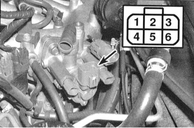
2. To check the IAC valve, measure the resistance between the corresponding terminals of its connector. At a temperature of 20°C, the resistance should be approximately 30 ohms. If no abnormalities can be found, the car should be taken to a service station for a detailed diagnosis of the PCM.
Replacement
1. Disconnect the electrical wiring from the IAC valve.
2. On 1993 and 1994 models, disconnect the hose from the valve housing. Remove the four mounting bolts and release the valve from the intake manifold.
3. On 1995 and later models, remove the two mounting screws and remove the valve from the housing.
4. Wipe the outer surface of the valve and the walls of its seat with a clean cloth.
Attention! Do not wash the valve with any solvent under any circumstances!
5. Place a new sealing ring into the housing and lubricate it with liquid machine oil.
6. Install the valve in its original place and tighten the fasteners securely.
7. Further installation is carried out in the reverse order of dismantling of the corresponding components.
Fast Idle Speed Control Solenoid Valve
On models from 1995 onwards, there are two electromagnetic valves controlling the fast idle speed. The valves ensure the stability of the engine speed regardless of the current load change. One valve is activated when the power steering is activated, the second when the air conditioner is turned on. Activation of the valves leads to an increase in the intensity of the air flow sucked into the intake manifold. System failure is not monitored by OBD.
Examination
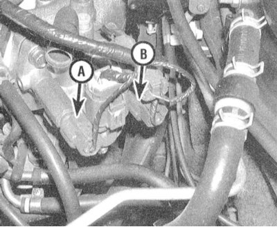
A — Electromagnetic valve for compensating for the increase in load associated with the operation of the power steering
B — Electromagnetic valve for compensating the increase in load associated with the operation of the K/V
1. Start the engine and turn the steering wheel all the way in either direction, then return it to the center position - the engine speed should not change, turning on the K/V should also not lead to a change in speed, otherwise check the condition of the corresponding electromagnetic valve.
2. Disconnect the electrical wiring from the solenoid valve. Connect the positive probe of the voltmeter to the terminal of the red-yellow or yellow-blue wire of the wiring harness on the connector. Ground the negative probe. With the ignition on and the K/V on, there should be battery voltage at the valve connector B, otherwise, you should check the condition of the electrical wiring in the section of the circuit between the valve and the fuse box (don't forget to check the condition of the corresponding fuses). If the A/C compressor clutch does not engage when the system is turned on, also check the condition of the corresponding relay. Check the condition of the PSP switch-sensor (see section Checking the condition and replacing the pressure switch in the power steering system (PSP)) and the quality of its grounding.
3. Switch off the ignition. Using a pair of jumper wires, apply power from the battery to the terminals of the corresponding solenoid valve - you should hear a clearly audible click, otherwise the valve should be replaced. Remove the valve (see below) and check the freedom of movement of its plunger. If the plunger is jammed or the retaining spring is broken, the valve must also be replaced.
Replacement
1. Disconnect the wiring from the fast idle speed control solenoid valve.
2. Using a wrench, release the valve from the IAC valve housing.
3. Replace the copper sealing washer, then screw the valve back into place and tighten it securely.
4. Further installation is carried out in the reverse order of dismantling of the corresponding components.
Fast Idle Cam
The fast idle cam is a thermocouple and is used on 1995 and later models to increase idle speed when starting a cold engine. While the engine is cold, the thermocouple plunger remains in its normal position and the fast idle cam acts on the throttle lever, slightly moving it away from the stop, which increases the engine's idle speed. As the engine warms up, the plunger retracts and rotates the cam so that the lever returns to its base position.
Checking and adjusting
Note: Performing the following procedure may cause a fault to be stored in the OBD memory and the Check Engine Light to be illuminated. Once the check and any necessary repairs have been completed, be sure to clear the system memory (see section On-Board Diagnostics (OBD) System - Operating Principle and Error Codes).
1. Disconnect the wiring from the ECT sensor and connect an ohmmeter to the two terminals of the latter (see section Checking the condition and replacing the engine coolant temperature sensor (ECT)).
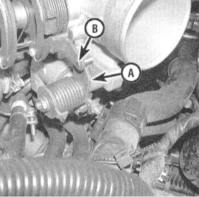
2. Start the engine and observe the change in resistance of the temperature sensor. When the resistance of the sensor reaches 1650÷2400 Ohm, the long mark on the fast idle cam should be aligned with the central part of the actuator lever pin.
3. Do not turn off the engine - when the resistance of the ECT sensor drops to 260÷390 Ohm, the short mark of the cam should be aligned with the central part of the finger, otherwise, loosen the lock nut and turn the adjusting screw to achieve the desired result.
4. If the cam cannot be adjusted, the throttle body should be replaced (see Chapter Power and exhaust systems).
The material is based on data from the portal nissanbook.ru