Examination
Note. Performing the procedure described below may lead to the entry into the OBD memory of a malfunction, which will be highlighted by a control lamp "Check engine". Upon completion of the check and the corresponding remedial repair, do not forget to clear the system memory (see Section On-Board Diagnostic System (OBD) - the principle of operation and fault codes).
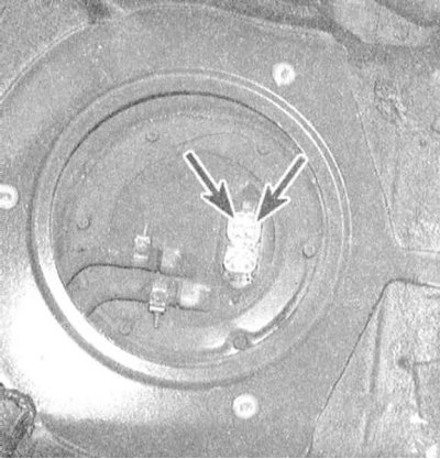
1. Remove rear seat and fuel pump/fuel flow sensor assembly access cover (see chapter Power and exhaust systems).
2. Make sure that the fuel supply to the temperature sensor is in good condition. Disconnect the wiring harness from the fuel flow/temperature sensor assembly. Connect the positive probe of the voltmeter to the pink-blue wire terminal of the connector, the negative one to the black wire terminal. With the ignition on, the meter reading should be 5.0 V, otherwise check the condition of the wiring in the sections of the circuit between the sensor and the PCM/ground. If the wiring is OK, drive the vehicle to a workshop to have the control module diagnosed and repaired accordingly.
3. Using an ohmmeter, measure the resistance between the two terminals of the fuel temperature sensor. At room temperature (20°C) the resistance of the sensor should be 2300 ÷ 2700 Ohm. A more accurate check of the correct functioning of the sensor can be made by removing it from the car and lowering it into a vessel with water heated over a fire. Compare the measurement results with the resistance change map. A defective sensor must be replaced.
Replacement
1. Remove the fuel flow sensor assembly from the tank (see chapter Power and exhaust systems).
2. Remove the fuel temperature sensor from the assembly.
3. Installation is carried out in the reverse order.