Scheme of operation of a typical EGR backpressure sensor
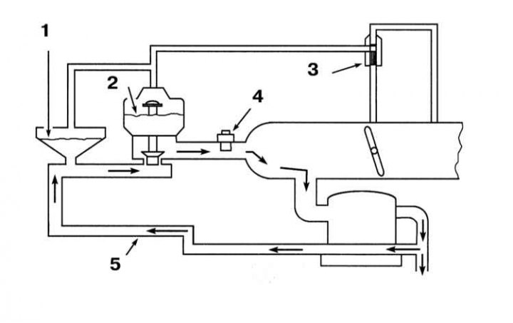
1 - Valve-switch VRT; 2 - EGR valve; 3 - Electromagnetic EGRS; 4 - EGR temperature sensor; 5 - EGR pipe
In order to reduce the emission of nitrogen oxides into the atmosphere, the engine design provides for the removal of part of the exhaust gases into the intake pipeline through the EGR valve. This admixture of exhaust gases to the air-fuel mixture leads to a decrease in its combustion temperature.
Models for 1998 vol.
1. On models up to 1998, no. EGR system includes EGR valve, control solenoid valve (EGRC), associated with vacuum in the port and pipeline, EGR temperature sensor and backpressure sensor valve (ART). The PCM controls the operation of the system through the EGRC solenoid valve. A special valve is provided in the intake air path, located directly behind the throttle valve. The intake port vacuum is monitored through a valve located in the throttle body. When accelerating, the throttle valve opens, which leads to an increase in the depth of vacuum in the intake manifold.
2. The BRT switch valve monitors the depth of the exhaust back pressure as the engine RPM changes. Information from the EGR temperature sensor is used by the PCM to control EGR flow by turning the system on/off.
System check
1. Check all hoses for cracks, twists and other mechanical damage. Assess the tightness of the union connections.
2. To check the correct operation of the EGR system, warm up the engine to normal operating temperature. Shift the transmission to neutral, apply the parking brake and chock the rear wheels of the vehicle. Leave the engine running at idle. After opening the throttle, raise the engine speed to 2000 ÷ 4000 rpm, then close the throttle again, - the EGR valve stem should move with a change in speed. Repeat the test several times. If the stem does not move. Check the vacuum signal supply to the EGR valve. Disconnect the hose from the valve and, pressing your finger against its cut, repeat the procedure. If there is no vacuum in the hose, check the tightness of the corresponding nipple connections, then proceed to check the EGRC solenoid valve.
Component Check
EGR valve
1. With the engine off, disconnect the vacuum hose and use a hand vacuum pump to create a vacuum on the EGR valve about 25.4 mm deep. rt. Art. if the valve opens, measure its stroke, which should be about 3 mm. Replace defective valve.
2. Re-vacuum and pinch the hose. The valve must remain open for at least 30 seconds, otherwise the diaphragm will fail and the assembly must be replaced.
3. Start the engine and apply vacuum to the valve. When the valve is open, there should be a violation of the stability of the idle speed, otherwise you should make sure that there are no violations of the patency of the channels in the intake manifold. If there are no changes in engine speed when opening and closing the valve, it is possible that the latter is generally stuck in one of the positions. Remove the EGR valve and check the poppet and its seat for foreign deposits.
4. In case of strong carbon formation, the valve should be wiped with solvent, making sure that it does not come into contact with the diaphragm.
5. Using a manual vacuum pump, hold the valve in the open position and carefully scrape off the solvent-softened layer of deposits from the working surfaces of the poppet and its seat. Assess the degree of wear of the working components, if necessary, replace the valve assembly.
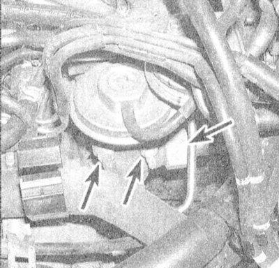
EGR control solenoid valve (EGRC)
1. Check up serviceability of giving on the vacuum valve at the working engine. If there is no vacuum, check the condition of the respective vacuum hoses and their fittings. If the hoses are in order, check the patency of the fitting on the throttle body. If the vacuum is supplied properly, disconnect the electrical wiring from the EGRC valve and check the battery voltage supply to the contact terminals of the battery voltage connector with the ignition on (do not start the engine).
2. To check the correct functioning of the EGRC solenoid valve, disconnect the electrical wiring from it and, having grounded one terminal, connect the second terminal to the positive pole of the battery using a jumper wire.
3. When power is applied, air must flow freely through the two fittings located next to each other. When the power is turned off, the valve should close.
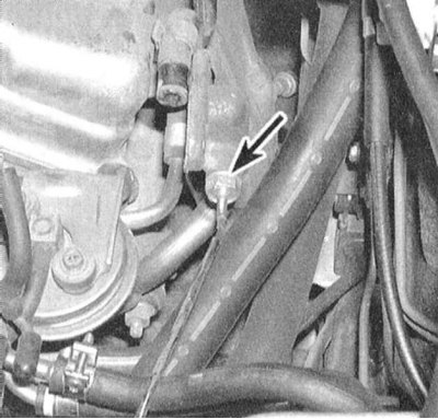
EGR backpressure switch valve (ART)
Locate the BRT switch valve and plug one of its fittings with your finger. Using a hand vacuum pump, create a vacuum in the switch valve. The VRT should allow a small amount of leakage. Note: Vacuum loss must stop when a pressure of 1.0 kPa is applied to the nozzle located under the valve (the valve must be removed from the vehicle). A defective switch valve must be replaced.
EGR temperature sensor
Remove the EGR temperature sensor. Dip the probe tip into a container of water. Start heating the water by monitoring the change in the resistance of the sensor. As the temperature increases, the resistance should fall and at 100°C reach a value of 80 ÷ 100 kOhm.
Component Replacement
EGR valve
1. Disconnect the air intake sleeve from the throttle body and air cleaner assembly (see chapter Power and exhaust systems).
2. Disconnect the vacuum line from the EGR valve. Give a nut of union connection.
3. Release the fixing clips.
4. Remove the EGR valve from the inlet pipeline. The old gasket cannot be reused and must be replaced without fail during installation.
5. Use a wire nozzle to clean the surface of the inlet pipeline mating with the valve. If the valve will not be replaced, also clean its mating surface. Use a screwdriver to scrape off the carbon deposits.
Attention! To avoid damage to the diaphragm, never wash the valve in solvents! It is also not recommended to resort to sandblasting of the mating surface.
6. If there is excessive carbon formation, the EGR passages can be cleaned with a wire brush. Ensure that all abrasive is thoroughly removed to avoid blocking the valve.
7. If the valve is very dirty, remove the EGR pipe from the exhaust manifold and clean it from the inside. Note: Remove the BPT switch valve and carefully remove abrasive from all channels.
8. Installation is carried out in the reverse order.
Solenoid valve EGRC
1. Disconnect from the EGR control solenoid (EGRC) wiring.
2. Carefully label and disconnect all vacuum tubes.
3. Give a fixing nut and remove the electromagnetic valve.
4. Installation is carried out in the reverse order.
EGR temperature sensor
1. Disconnect the electrical wiring from the sensor and unscrew the latter from the tube.
2. Lubricate the sensor threads with anti-seize sealant before installation.
3. Installation is carried out in the reverse order.
Models 1999 vol.
On models 199 issue. The EGR system consists of an EGR valve based on the principle of a stepper motor, an EGR temperature sensor and a control module (RSM). The PCM controls the EGR flow by opening and closing the EGR valve in small steps. The system allows for fine metering of the EGR flow, maximizing engine performance.
Component Check
EGR valve
1. Check the power supply to the EGR valve. Disconnect the wiring and turn on the ignition. ground the negative probe of the voltmeter to ground, connect the positive one to the terminals of the two red wires of the connector in turn. In both cases, the meter must register the battery voltage, otherwise you should check the condition of the wiring in the sections of the circuit between the battery and the ECCS relay (don't forget the fuses), and relay and EGR valve (see wiring diagram at the end of the Chapter Onboard electrical equipment).
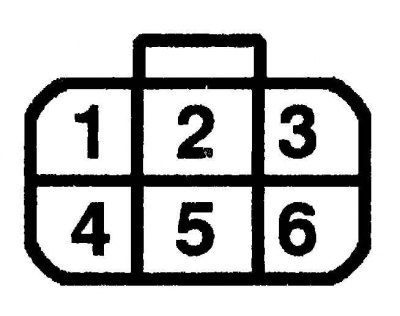
2. Using an ohmmeter, measure the resistance between the respective terminals of the EGR valve connector. At room temperature (20°C) the measurement result should be 22 ohms, otherwise replace the valve. If the valve is in order, the vehicle should be driven to a workshop for PCM diagnostics and necessary remedial repairs.
EGR temperature sensor
Remove the EGR temperature sensor. Dip the probe tip into a container of water. Start heating the water by monitoring the change in the resistance of the sensor. As the temperature increases, the resistance should fall and at 100°C reach a value of 10 ÷ 30 kOhm.
Component Replacement
EGR valve
1. Disconnect the air intake sleeve from the throttle body and air cleaner assembly (see chapter Power and exhaust systems).
2. Set aside hoses and electrical wiring to provide access to the EGR valve.
3. Disconnect the EGR pipe.
4. Release the fasteners.
5. Remove the EGR valve from the intake manifold. The old gasket cannot be reused and must be replaced without fail during installation.
6. Using a scraper, carefully clean the mating surfaces of the valve and pipeline.
7. Installation is carried out in the reverse order.
EGR temperature sensor
1. Disconnect the electrical wiring from the sensor and unscrew the latter from the pipeline.
2. Lubricate the sensor threads with anti-seize sealant before installation.
3. Installation is carried out in the reverse order.