


Table of contents: Operating principle ↓ Checking the system's functionality ↓ Checking the EGR valve ↓ Checking the modulating valve ↓ Checking the thermal vacuum valve ↓
Note: A hand vacuum pump with a vacuum gauge will be required to perform system component maintenance procedures.
Operating principle
The operating principle of the EGR system
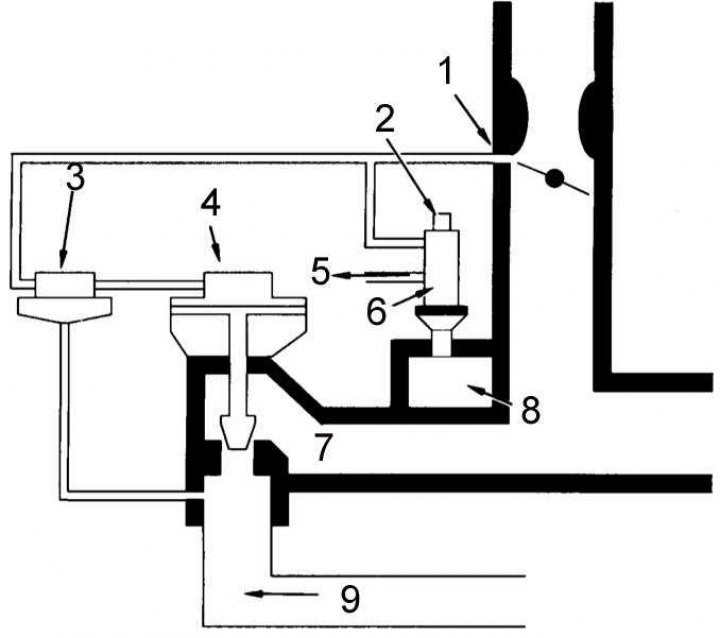
1 - control vacuum nipple; 2 - atmosphere; 3 - modulating valve; 4 - EGR control valve; 5 - to distributor 6 - TVV; 7 - inlet manifold; 8 - coolant; 9 - exhaust gases
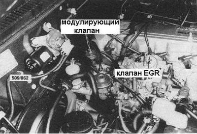
In order to reduce the level of nitrogen oxides in the exhaust system, a portion of the exhaust gases is sent back to the engine. The main components of the recirculation system are the EGR valve, the modulating valve and the thermal vacuum valve (TVV) (the location of the first two on the engine is shown in the accompanying illustration).
The modulating valve controls the depth of vacuum supplied to the EGR valve in order to maintain a constant level of exhaust gas recirculation.
At low coolant temperatures, the TVV is closed and blocks the vacuum from reaching the EGR valve, keeping the latter closed as well.
When the coolant temperature reaches normal operating temperature, the TVV opens, allowing vacuum to reach the modulating valve.
The modulating valve diaphragm is pressed by exhaust gases from the exhaust system and provides or closes the air supply to the vacuum tube of the EGR valve, thereby controlling the opening/closing of the latter.
At low loads or low engine speeds, when the exhaust pressure is low, the diaphragm spring overcomes this pressure, opening the air supply. Accordingly, the EGR valve remains closed.
At high engine loads/speeds, the exhaust gas pressure also rises, overcoming the resistance of the diaphragm spring and blocking the air supply. At the same time, the EGR valve is affected by the full depth of the vacuum, which increases the level of exhaust gas recirculation.
Checking the system's functionality
1. Check the condition of all vacuum hoses. Replace defective ones.
2. Start the engine and warm it up to normal operating temperature. With the engine running, open and close the throttle valve, observing the behavior of the EGR diaphragm. The EGR valve should open and close simultaneously with the valve.
3. If the test conditions are not met, check the system components individually.
Checking the EGR valve
4. Stop the engine and disconnect the vacuum supply line from the EGR valve.
5. Connect a hand vacuum pump with a vacuum gauge to the EGR valve and create a vacuum of 120 mmHg.
6. The valve should open smoothly and remain open until the vacuum is released, otherwise it must be replaced.
Checking the modulating valve
1. Insert a piece of wire of suitable length into the lower fitting of the modulating valve.
2. Slightly depress the diaphragm and use a hand vacuum pump to create a vacuum on the upper valve nipple.
3. If the valve does not hold the vacuum, it can be considered faulty.
4. Checking the thermal vacuum valve
5. Start the engine from a cold state. Disconnect the vacuum hose from the upper fitting of the modulating valve.
6. Place your finger on the open end of the hose and increase the engine speed. There should be no vacuum.
7. Warm up the engine to normal operating temperature. Again, place your finger on the end of the hose and increase the speed. You should now feel a vacuum.
8. Replace TVV if necessary (the location of the TVV on the engine is shown in the accompanying illustration).
Checking the thermal vacuum valve
1. Start the engine from a cold state. Disconnect the vacuum hose from the upper fitting of the modulating valve.
2. Place your finger on the open end of the hose and increase the engine speed. There should be no vacuum.
3. Warm up the engine to normal operating temperature. Put your finger on the end of the hose again and increase the speed. You should now feel a vacuum.
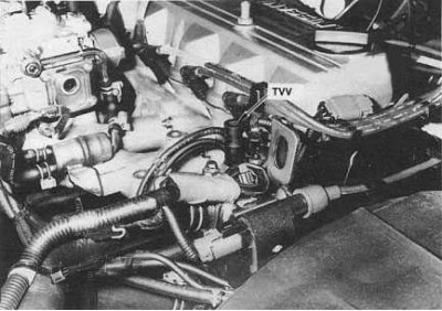
4. Replace TVV if necessary (the location of the TVV on the engine is shown in the accompanying illustration).