


Table of contents: Operating principle ↓ Service ↓
Operating principle
The ECS system is used to reduce the emission of hydrocarbon compounds from the fuel tank into the atmosphere.
The principle of operation of the system
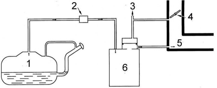
1 - fuel tank; 2 - one-way fuel control valve; 3 - to TVV (only 3.0 l); 4 - throttle valve; 5 - inlet manifold; 6 - carbon adsorber
The main components of the system include a charcoal canister, a purge control valve, a sealed fuel tank and, on 3.0L models, a thermal vacuum valve (TVV).
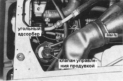
Location of purge control valve and charcoal canister on 4.2L models
When the engine is not running, fuel vapors gradually fill all the space in the gas tank free of fuel. Since the tank is equipped with a sealed lid, the vapor pressure rises and they are forced into the carbon adsorber, where they accumulate. A one-way control valve prevents liquid fuel from entering the adsorber.
When the engine is started, a small amount of vapor enters the intake manifold through the continuous purge throttle opening and is burned as part of the air-fuel mixture. As the engine speed increases, the main purge throttle opening of the adsorber opens, from which a larger volume of vapor accumulated during the standstill period is removed.
On 3.0L models, a special Thermal Vacuum Valve (TVV) is used to close the main throttle purge port at low engine temperatures.
Service
Note: The system should be serviced regularly, with particular attention to the following points.
1. Check the patency and external condition of all hoses in the system.
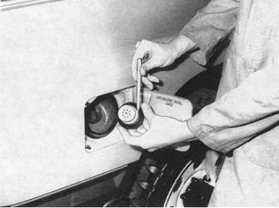
2. Check the condition of the fuel tank filler cap gasket (see accompanying illustration). Make sure that the vacuum relief valve is functioning properly.
3. Check the operation of the carbon adsorber and one-way control valve.
Checking the carbon adsorber
1. Inspect the canister for signs of damage or leaks. Replace if necessary.
2. Mark and disconnect the hoses from the canister.
3. Blow into the fitting of the upper purge control hose. No air should pass through.
4. Blow into the lower purge hose fitting. Air should flow freely.
5. Blow into the inlet hose fitting. Air should also be blown out.
6. Replace the adsorber if necessary.
Checking the one-way check valve
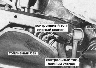
1. Remove the valve from the fuel tank (see accompanying illustration).
2. Blow into the valve nipple facing the fuel tank. No air should pass through.
3. Blow into the valve nipple located on the carbon adsorber side. The air passage should be free.
4. Replace the valve if necessary.