


Table of contents: Models with carburetor engine ↓ "Phase I" models (model year 1993,…↓ All other models with fuel injection ↓
Models with carburetor engine
Identifying Carbon Filter Hose Connections
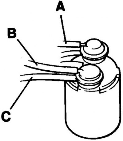
Examination
1. If you think the system is faulty, disconnect the hoses from the carbon filter and the thermal vacuum valve and blow them out.
2. To check the thermal vacuum valve, which is mounted on the right side of the intake manifold, when the engine is cold, disconnect both hoses from the valve. Connect the hose to one of the valve ports and blow into it. The valve should be closed and should not leak air. Start the engine and warm it up to normal operating temperature. Blow into the hose again; the valve should be open and air should flow freely. If the valve does not work as described above, replace it.
3. The carbon filter is located in the right rear corner of the engine compartment. The carbon filter and its valves can be checked as follows.
4. Go along the hose "A" from the carbon filter and disconnect it from the tee connection. Start the engine and try to suck air from the hose; the valve should not leak air and the engine speed should increase slightly. Reconnect the hose to the tee fitting.
5. Go along the "C" hose from the carbon filter and disconnect it from the carburetor float chamber. Start the engine and blow into the hose; the valve should not leak air. Reconnect the hose to the carburetor.
6. Go along the "B" hose from the carbon canister and disconnect it from the intake manifold. With the engine off, blow into the hose and suck air out of the hose; the valve should not allow air to pass in either direction. Reconnect the hose to the intake manifold.
7. If, during the checks described in points 4–6, there is an air leak through any of the hoses, the carbon filter and its valves must be replaced.
"Phase I" models (model year 1993, before June) with a 2.0 liter engine and multi-point fuel injection system
Examination
1. If you believe the system is faulty, disconnect the hoses from the carbon filter located in the right rear corner of the engine compartment and blow through them.
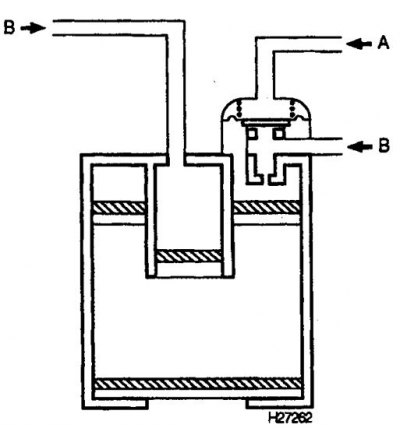
2. The carbon filter and its valves can be checked as follows: Disconnect the hoses from the carbon filter and blow into the "A" branch pipe; the valve should not let air through. Blow through each of the "B" pipes in turn. Both channels should be open and let air through freely. If the checks do not yield the expected results, the carbon filter and valves must be replaced.
All other models with fuel injection
Examination
1. If you suspect the system is faulty, disconnect the hoses from the carbon canister and solenoid valve and blow through them. On 1.6-liter models, the carbon canister is located in the left rear corner of the engine compartment, and the solenoid valve is located on the rear side of the intake manifold. On 2.0-liter models, the carbon canister is located on the left side of the engine compartment, and the solenoid valve is located on the left or lower side of the intake manifold.
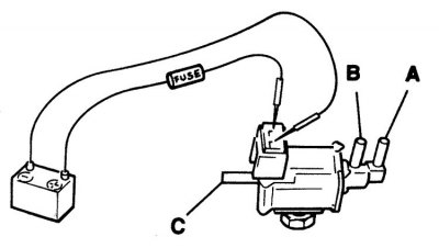
2. The solenoid valve can be tested using the wiring diagram provided.
(The material is taken from a web resource: www.NISSANBOOK.ru)
If necessary, remove the valve following the instructions provided in subsection 6.4.2.3.3, to improve access.
3. Blow into port "A" and check that no air passes through it. Blow into port "B" and check that air passes through this port and comes out of port "C".
4. Connect a 12-volt power source to the solenoid valve through the fuse as shown in the figure. After applying power, blow into port "A" and check that air passes through the valve and comes out of port "B". Blow into port "B" and check that air passes through the valve and comes out of port "C".
5. If the solenoid valve does not work as expected, it is faulty and needs to be replaced.
6. The carbon filter and valves can be checked as described higher.