Checking on carbureted engines
1. To check, disconnect the hoses from these valves and blow, the air should pass freely through the hoses.
2. The TBP check is described in subsection 6.4.1.1.2.
3. To check the recirculation valve, disconnect the vacuum hose at the top. Connect the auxiliary hose and create a vacuum in it. Check the diaphragm travel by placing your finger on the bottom of the valve. If the diaphragm is motionless, replace the valve.
4. If TVR is OK, then check the check valve. To do this, warm up the engine and disconnect the vacuum hose from the recirculation valve. Put your finger on the hose, sharply increase and slow down the engine speed. When the speed increases, a vacuum should be felt in the hose, which should slightly weaken when the speed drops. Otherwise, replace the check valve.
Injection engine test
The test procedure is the same as on a carburetor engine, with the exception that instead of TBP, a solenoid valve is checked.
The solenoid valve is no different from the EVAP valve and is tested in the same way (see subsection 6.4.1.1.2).
Recirculation valve
Replacement
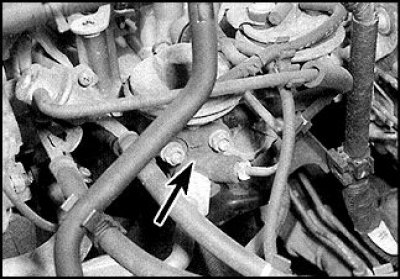
1. Recirculation valve on injection engine (indicated by an arrow) mounted on the left side of the suction manifold. To access the valve, it is recommended to remove the air filter and check valve. Disconnect the vacuum hose from the valve.
2. Loosen the union nuts and disconnect the recirculation and check valve tubes.
3. Remove 2 nuts, remove valve and gasket.
Check valve
Replacement
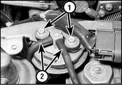
1. The valve is mounted on the left side of the suction manifold (1 - screws, 2 - vacuum hoses). To access the valve, it is recommended to remove the air filter.
2. Disconnect the vacuum hoses from the valve.
3. Loosen 2 screws and remove valve.
4. The valve is installed in reverse order.
TVR on a carburetor engine
Replacement
See subsection 6.4.1.1.2.
Solenoid valve on injection engine
Replacement
See subsection 6.4.1.1.2.
Exhaust gas control sensor
Checking on carbureted engines
1. Adjust the quality of the idle mixture.
2. Open the diagnostic connector, which is located under the fuse box.
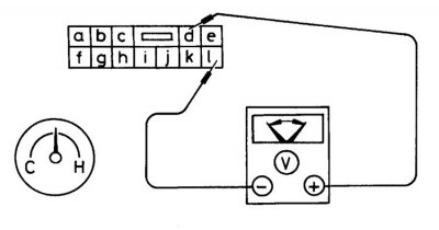
3. Connect a voltmeter to the terminals of the connector.
4. Start the engine, bring the speed to 2000 rpm and observe the voltmeter for 2 minutes. With a working sensor, the voltmeter readings should change five times from 0 to 12 V for every 10 seconds. Otherwise, the sensor is faulty and a more accurate check at a car service is necessary.
Injection engine test
If the CO content in the exhaust gases exceeds the norm, then it is necessary to check the serviceability of the exhaust gas sensor using the self-diagnosis function of the processor unit.
Converter
Replacement
See subsection 6.1.14 and subsection 6.2.16.
Exhaust gas sensor
Replacement
Attention! If dropped or subjected to strong shock, the sensor may be damaged.
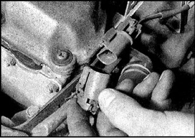
1. Disconnect the connector from the exhaust gas sensor.
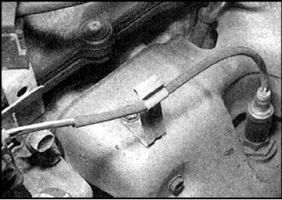
2. Remove the wires from the brackets.
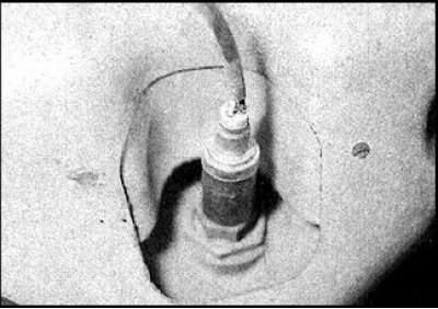
2. Turn out the gauge and remove together with a laying.
3. Install the sensor in reverse order. Lubricate the sensor threads with refractory grease.