


General information
1. The system is designed to capture gasoline vapors, preventing them from entering the atmosphere in the form of hydrocarbons (photo).
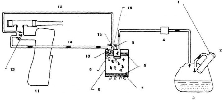
5.1 Design of the gasoline vapor recovery system
1. Plug with vacuum valve; 2. Vacuum relief; 3. Tank; 4. Check valve; 5. Diaphragm spring; 6. Screen; 7. Filter; 8. Tank with absorber; 9. Ventilation hole; 10. Control vent
2. The tank has a ventilation valve (photo) with two hoses. The valve has 2 holes, one of which (larger diameter) blocked by the diaphragm.
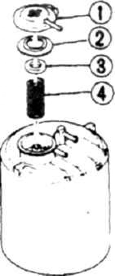
5.2a Tank details
1. Lid; 2. Diaphragm; 3. Limiter; 4. Spring
5.2b Tank valve vent
3. A control valve is installed between the tank with the absorber and the fuel tank, which is designed to ventilate the tank when the engine is running and to transfer vapors to the absorber when the engine is stopped (photo).
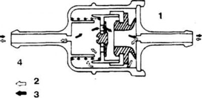
5.3 Check valve. Air should flow freely from the fuel tank side, and in the opposite direction the valve is closed
1. To the tank; 2. Gasoline vapors; 3. Air; 4. To the engine
4. Maintenance of the system consists of checking the condition of the tank, hoses and valves.
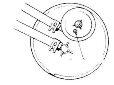
5. When checking the tank, air should not pass through the larger diameter vent hole and should pass freely through the purge line and vent valve (photo). Otherwise, replace the tank.
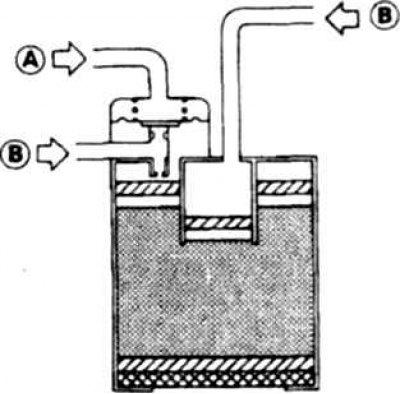
5.5 Tank check diagram. When blowing through the A connector, air should not pass through, air passes freely through both B connectors
6. The tank vacuum valve is faulty if, when sucking air through the valve from the tank side, no resistance is felt and there is no characteristic knocking sound.
7. The control valve should barely let air through from the tank side and let it through slightly when blowing from the absorber side. Replace valves that show a negative result when tested.