


Attention! On cars after 1996, diagnostics of failures in the fuel and auxiliary systems is performed only in a car service. There are no LED indicators on these cars.
Failure of sensors and actuators can be determined using diagnostic codes of the vehicle's ECCS processor system. There are 5 modes of operation of the self-diagnostic system.
Mode 1 - signals from the oxygen sensor. On a warm engine, the closed-loop automatic control mode operates. In this case, the green indicator lights up, indicating a lean mixture, or goes out, indicating a rich mixture. On a cold engine, regulation is performed in an open loop, the indicator either lights up constantly or goes out.
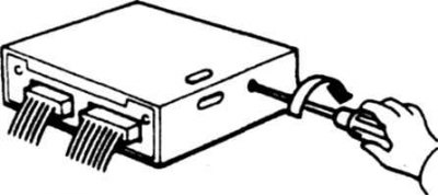
6.1 Setting the mode
Mode 2 - Monitoring feedback during stabilization of mixture stoichiometry. When the mixture composition stabilizes within certain limits, the red indicator flashes simultaneously with the green one. During the open control loop, the red indicator is constantly on (or off).
Mode 3 - self-diagnostic mode. All failures are recorded in memory. The memory contents are erased after 50 starter activations or when the power supply to the processor unit is interrupted.
Mode 4 - diagnostics of the condition of the throttle switches, starter, vehicle speed sensor, etc.
Mode 5 - real-time diagnostics for on-road testing.
Select mode (engine with direct fuel injection system, 1990-1995.)
Turn on the ignition and turn the mode switch clockwise (photo) until it stops, wait until the lamp starts flashing. After the number of lamp flashes becomes equal to the number of the selected mode, immediately turn the mode switch counterclockwise. Do not turn off the ignition, otherwise mode 1 will be set automatically.
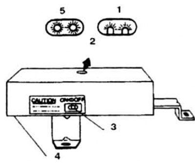
6.2 To set the mode, move the switch to the left
1. Side view; 2. Inspection window for signal lamps; 3. Mode switch; 4. Processor unit; 5. Top view
To check the codes, warm up the engine and set mode 3. To determine the code, count the number of flashes of the green and red lamps (the number of units and tens, respectively). When finished, delete the memory contents by turning the switch clockwise (setting mode 4), and then counterclockwise.
Diagnostic codes and corresponding faulty circuits and sensors
| 11 | Crankshaft Position Sensor Circuit |
| 12 | Flow meter circuit |
| 13 | Temperature sensor circuit |
| 14 | Speed sensor circuit |
| 21 | Ignition signal circuit |
| 31 | Processor unit |
| 32 | Recirculation system failure |
| 33 | Oxygen sensor |
| 34 | Knock sensor |
| 35 | Exhaust gas temperature sensor |
| 41 | Air temperature sensor |
| 43 | Throttle Position Sensor |
| 45 | Leak in the nozzle |
| 51 | Injector chain |
| 55 | Normal operation of the on-board processor |
Selecting a mode on an engine with a preliminary injection system (with TBI system)
If necessary, determine the mode code (for example, in the event of a sharp deterioration in engine performance) remove the processor unit from under the passenger seat. Do not disconnect the connectors, as this will destroy the stored codes. Turn on the ignition and move the mode selector switch to the on position (photo) the red and green indicators will start flashing. After 3 flashes of the indicators (mode 3 is set), turn the switch to the off position. To determine the code, count the number of flashes of the green and red lamps (the number of units and tens, respectively).
When finished, clear the memory contents by setting mode 4 or disconnecting the battery from ground. When setting mode 4, the indicators should flash 4 times.