


Table of contents: Examination ↓ Replacement ↓
1. The exhaust gas after-oxidation system reduces the content of hydrocarbons and CO in emissions by injecting filtered air into the exhaust manifold. The exhaust gas after-oxidation system of injection engines consists of an electromagnetic vacuum cut-off valve (photo), controlled from the processor unit, reed valves with filters, a flame arrester and ejector tubes.
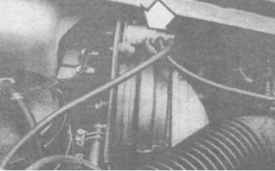
4.1a Electromagnetic shut-off valve regulating the vacuum in the post-oxidation system
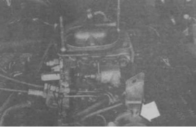
4.1b The flame arrester on the injection engine is mounted on the intake manifold in front of the valve body
Examination
2. Inspect the condition of all hoses.
3. Disconnect the hoses from the ejector tube, plug the tube with your finger while the engine is idling. As the engine speed increases, you should feel an increasing vacuum on the tube. Otherwise, the tube is damaged or clogged.
4. To check the flame arrester, remove the air filter and disconnect the hose from the flame arrester. Warm up the engine. Plug the flame arrester nipple with your finger, bring the speed to 3000 rpm and sharply release the throttle valve. When switching to idle, a sharp increase in vacuum should be felt. Otherwise, replace the flame arrester.
Replacement
Filter and reed valve
5. See Chapter 1.
Reed valve body
6. Disconnect the hose from the valve body, unscrew the screws and remove the body (is located in the left corner of the engine compartment, photo).
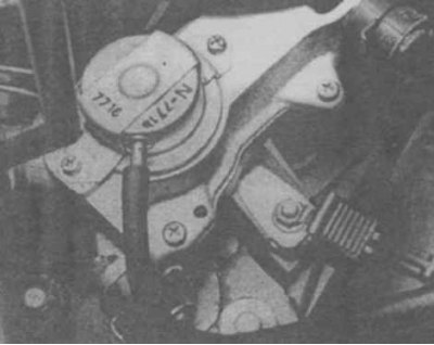
4.6 Reed valve body
7. Check the condition of the reed valve. Replace if necessary by prying and pushing the valve out of the housing.
8. Installation is performed in reverse order. Check the correct installation of the valve (photo). Secure the hoses with clamps.
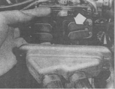
4.8 Installing the reed valves. Check the tightening of the "limiter" screws (arrow)
Tube
9. Remove the tube assembly with the valve body, for which unscrew the body screws, the fitting on the exhaust manifold (lubricate with penetrating fluid) and the bracket bolt. Disconnect the tube hoses from the body.
10. Installation is performed in reverse order. Lubricate the fitting with a compound to prevent the threads from seizing.
Flame arrester
11. Remove the air filter and disconnect the hoses from the flame arrester (photo). Installation is performed in the reverse order.
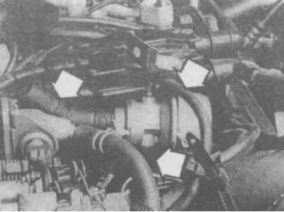
4.11 Flame Arrestor Hoses on V6 Engine (shown with air filter removed)