


Engine Temperature Sensor - Check
1. The sensor needs to be checked if the engine has difficulty starting and if code 13 is detected in self-diagnostic mode (see above).
2. If the engine does not start and there are obvious signs of incomplete combustion of fuel, then disconnect the connector and try to start again. If the engine does not start, then unscrew the sensor and check its resistance depending on the temperature (photo). If the resistance differs from the norm, then replace the sensor. Otherwise, check the sensor circuit.
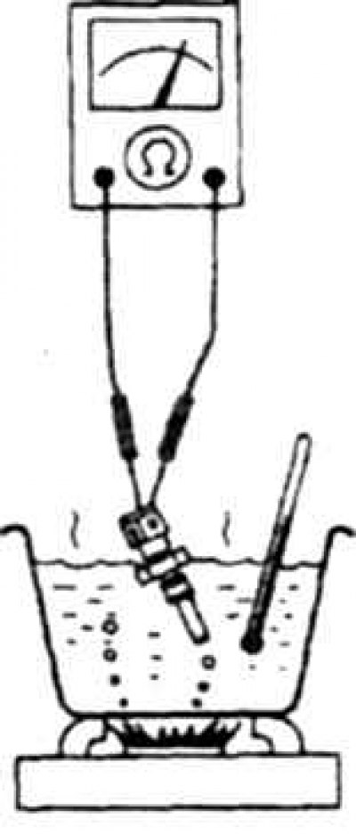
9.2 Checking the engine temperature sensor
3. Install the sensor in reverse order.
Checking the exhaust gas temperature sensor
4. The sensor needs to be checked if code 35 is detected in self-diagnostic mode (see above).
5. If the engine runs unsteadily in cruise control mode, disconnect the connector and check the car's running (photo).
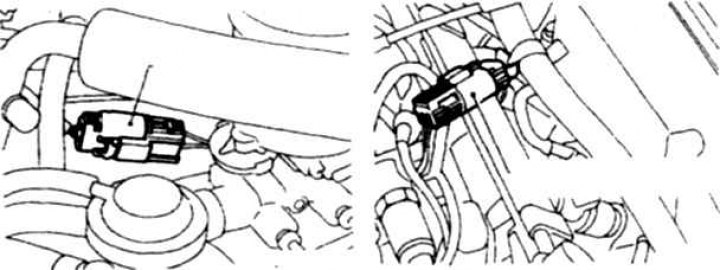
9.5 Exhaust gas temperature sensor connector on V6 and K24 engines
6. If the car's running has improved, replace the sensor. Otherwise, turn on the ignition and check the voltage at the connector terminal, which should be about 5 V (photo).
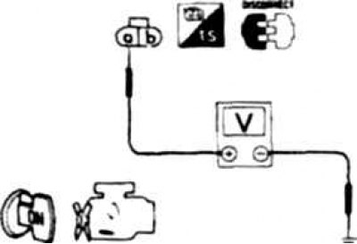
9.6 Checking the voltage between the sensor connector terminal and ground
7. Turn off the ignition and check the circuit for ground (photo).
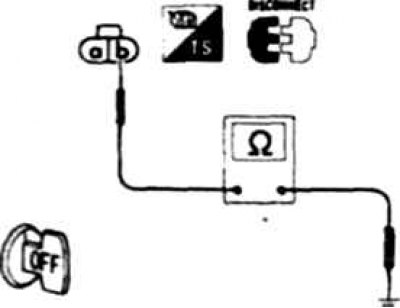
9.7 Checking the sensor connector output circuit to ground
8. If the voltage differs from 5 V or there is a break in the circuit, replace the sensor.
Checking the oxygen sensor
9. The sensor needs to be checked if code 33 is detected in self-diagnostic mode (see above).
10. If the engine runs unsteadily in cruise control mode, disconnect the connector and check the car's running (photo).
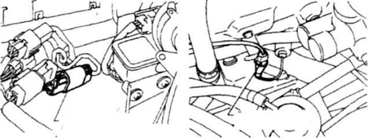
9.10 Oxygen sensor connector on V6 and KS4 engines
11. If the car's running has improved, replace the sensor. Otherwise, increase the speed to 2000 rpm and after 2 minutes, make sure that the green signal is flashing on the processor unit.
12. On V6 engines, with the ignition on, check the voltage between connector terminal A and ground, which should be about 12 V (photo).
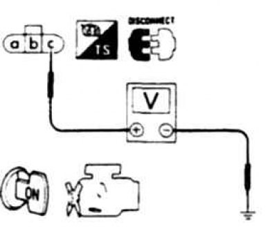
9.12 Checking the voltage at the oxygen sensor connector terminal
13. Turn off the ignition and check the circuit for ground (photo).
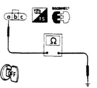
9.13 Checking the Oxygen Sensor Circuit for Ground on V6 Engines
Attention! On V6 engines, the ohmmeter circuit should show a circuit between terminal A and ground, and on the K24 engine, between terminal A and terminal 19 of the connector on the processor unit.
14. If the voltage differs from 12 V or there is a break in the circuit, replace the sensor.
Checking and replacing the air temperature sensor (on the K24 engine)
15. The sensor needs to be checked if code 41 is detected in self-diagnostic mode (see above).
16. Disconnect the sensor connector (photo) and with the ignition on, check the voltage between connector terminal B and ground, which should be about 5 V (photo).
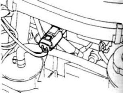
9.16a Air temperature sensor connector on K24 engines
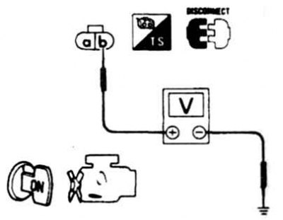
9.16b Checking the voltage at the air temperature sensor connector terminal
17. If the voltage is normal, turn off the ignition and check the circuit between terminal A and ground.
18. Check the sensor resistance, which should be 2.1-2.9 Ohm at 20°C and 270-300 Ohm at 80°C.
19. If replacement is necessary, unscrew the sensor from the air filter and screw in a new one.