General information
The λ-probe located in the exhaust tract of the engine monitors the oxygen content in the exhaust gas stream. When O2 molecules come into contact with the sensitive element of the probe, the sensor generates an amplitude signal in the range from 0.1 to 0.9 V, depending on the oxygen concentration. Moreover, the value of 0.1 V corresponds to a high content of O2 (lean mixture), and a value of 0.9 V - low (rich mixture). The upstream oxygen sensor outputs to the PCM provides the control module with information about the residual O2 content in the exhaust system. The PCM continuously monitors the signal coming from the oxygen sensor, if necessary, issuing commands to adjust the composition of the air-fuel mixture by changing the duration of the opening of the injection injectors. The optimal ratio of the components of the combustible mixture, which guarantees the minimum fuel consumption with the most efficient functioning of the catalytic converter, is 14.7 parts of air per 1 part of the fuel, which is what the control module tries to constantly maintain, focusing on the information coming from the λ-probe.
The low-flow λ-probe has no effect on the air-fuel mixture control module's assembly process. By design and principle of operation, the sensor is identical to the upper flow sensor. By comparing the level of oxygen in the sections of the exhaust tract above and below the catalytic converter, the PCM determines the efficiency of the functioning of the latter. Note: On 1993 and 1994 models. issue only one oxygen sensor is used (upper flow). On models since 1995, no. two high-flow λ-probes are provided (one for each row of cylinders) and one downstream.
It should be noted that the oxygen sensor is only capable of generating a signal voltage when warmed up to normal operating temperature (318°С). While the sensor is cold, the PCM operates in OPEN LOOP mode, controlling the air-fuel ratio based on its base parameters. The correct functioning of the oxygen sensor depends on the fulfillment of a combination of certain specific conditions:
- a) Electrical parameters: The stability of the low voltage amplitude signal generated by the sensor depends to a large extent on the quality of the contact connections of the λ-probe circuit, which should be checked first of all in case of problems;
- b) Outside air supply: The design of the λ-probe provides for the free circulation of outside air inside the sensor. When installing the probe, always check the patency of the air channels;
- c) Operating Temperature: The PCM only responds to information from the λ probe after the probe has warmed up to normal operating temperature (about 320°C). This fact should not be overlooked when checking the correct operation of the probe;
- d) Fuel quality: Proper functioning of the λ-probe becomes possible only if UNLEADED fuel is used for refueling the car!
In addition to the conditions listed in the previous paragraph, some special precautions must be observed when servicing the λ-probe:
- a) The oxygen sensor is equipped with a piece of electrical wiring permanently mounted into it, equipped with a contact plug, attempts to disconnect which can lead to irreversible failure of the probe;
- b) Try to keep the sensor louvers or its electrical connector free of dirt and grease;
- c) Do not use any solvents to clean the oxygen sensor;
- d) Handle the λ-probe with extreme care, do not drop it and try not to shake it off;
- e) The silicone protective cover must be worn on the sensor in a strictly defined way so as not to be melted and not to impair the proper functioning of the probe.
In the event of a malfunction of the λ-probe or its circuit, the PCM switches to open-loop mode, ignoring the information coming from the sensors and maintaining the composition of the air-fuel mixture at a certain predetermined level, which ensures sufficient efficiency of the engine output.
Examination
Attention! Oxygen sensors are extremely sensitive to electrical circuit overloads. To connect a voltmeter to the λ-probe connector, use jumper wires equipped with fuses. Try to very carefully insert the probes of the meter to the connector on its reverse side (see chapter Onboard electrical equipment). Use only digital meters to test sensors.
Performing the procedure described below may lead to the entry into the OBD memory of a malfunction, which will be highlighted by a control lamp "Check engine". After completing the check and the corresponding remedial repair, do not forget to clear the system memory (see Section On-Board Diagnostic System (OBD) - the principle of operation and fault codes).
1. Locate the sensor's electrical connector. On the reverse side of the connector, connect the positive probe of the voltmeter to the white wire terminal (see chapter Onboard electrical equipment). Ground negative probe. Start the engine and warm it up to normal operating temperature. According to the voltmeter readings, determine the value of the signal voltage of the sensor:
- a) The amplitude of the signal generated by the high-flow sensor should lie in the range from 100 to 900 mV, actively changing within the specified limits.
- b) The downstream sensor must produce a signal voltage in the same range (average 400 mV), but without active changes.
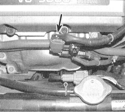 |  |
2. Check the battery voltage supply to the sensor. Assess the quality of the ground. Disconnect the electrical wiring from the sensor and connect the positive probe of the voltmeter to the green-black terminal (1993 and 1994) /red-black (since 1995) pin connector (see wiring diagrams at the end of the Chapter Onboard electrical equipment). Connect the negative wire to the blue/blue/yellow wire terminal. With the ignition on, the instrument should register a voltage close to the battery voltage.
3. Check the resistance of the oxygen sensor heating element. Connect an ohmmeter to the two terminals of the heating element in the wiring connector of the λ-probe (by the latter). Note: The wiring harness built into the transmitter is usually not color coded.
The required resistance is:
- a) For 1993 and 1994 models issue - 3.0÷1000 Ohm;
- b) For models 1995 and 1996 issue - 2.3÷4.3 Ohm (upstream sensors) and 5.2÷8.2 downstream;
- c) For models since 1997 vol. - 2.3÷4.3 Ohm.
4. If a break is detected, or if the measurement results are excessively high. Replace the appropriate sensor.
Note. If the results of the above checks are positive, you should check for an open and a short circuit in the wiring in the circuit between the sensor and the PCM. If no deviations can be detected, the car should be driven to a service station for more detailed diagnostics.
Replacement
1. Turning out the λ-probe on a cold engine can be extremely difficult due to thermal compression of the metal of the exhaust manifold/pipe of the exhaust system. To avoid the risk of damage to components, warm up the engine for a couple of minutes before proceeding with the removal of the sensor - try not to burn yourself on the heated surfaces during the procedure:
- a) Oxygen sensors are equipped with a built-in wiring harness with a connector. Damage to this harness leads to irreversible failure of the sensor - be careful;
- b) Try not to get oil, grease, dirt, moisture, etc. on the contact connector and sensor blinds;
- c) NEVER use any solvents to clean the sensor;
- d) Try not to drop or abruptly shake off the sensor.
2. Jack up the car and put it on stands.
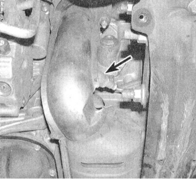
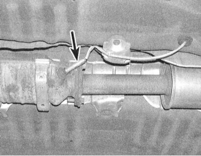
3. Carefully disconnect the oxygen sensor harness connector.
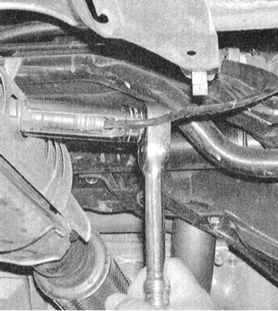
4. Using a special key, carefully unscrew the probe from the appropriate section of the exhaust system.
5. Before screwing in the sensor, lubricate its threaded part with an anti-seize sealant.
6. Screw the sensor into place and tighten it firmly.
7. Lower the vehicle to the ground and connect the wiring to the sensor.
8. Carry out a road test. Check the control module memory for trouble codes.