


Table of contents: Examination ↓ Replacement ↓
The ECT sensor is also a thermistor (see section Checking the condition and replacing the intake air temperature (IAT) sensor). On 1993 and 1994 models, the sensor is located in the water inlet pipe behind the distributor, on 1995 and later models, in the outlet pipe behind the left (front) cylinder head. Changing the resistance of the sensor has a direct effect on the amplitude of the signal it sends to the PCM. At the same time, as the temperature DECREASE, the resistance of the sensor INCREASES, and vice versa. The PCM uses the information supplied by the sensor to determine the operating temperature of the engine. Failure of the ECT sensor/a malfunction in its electrical circuit results in the recording of a corresponding code in the memory unit of the self-diagnostic system (see section On-Board Diagnostics (OBD) System - Operating Principle and Error Codes).
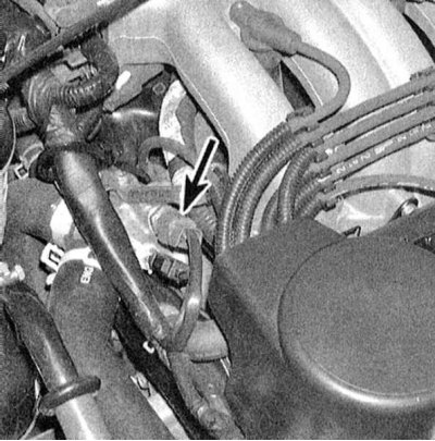 |
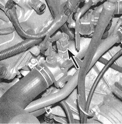 |
Examination
Note: Performing the following procedure may cause a fault to be stored in the OBD memory and the Check Engine Light to be illuminated. Once the check and any necessary repairs have been completed, be sure to clear the system memory (see section On-Board Diagnostics (OBD) System - Operating Principle and Error Codes).
1. Before proceeding directly to assessing the condition of the sensor, make sure that the power supply to it from the PCM is working properly and that there are no signs of ground faults. Disconnect the electrical wiring from the ECT sensor and connect a voltmeter to the two terminals of the connector on the harness side. Turn on the ignition (do not start the engine), - the meter should give a reading of 5.0 V, otherwise check the condition of the wiring in the circuit section between the sensor and the PCM. If the circuit is OK, drive the car to a service station to diagnose the condition of the PCM and perform the appropriate repair.
2. With the ignition off, disconnect the wiring from the ECT sensor and use an ohmmeter to measure the resistance between the two terminals of the sensor connector when the engine is cold. Restore the original wiring connection, start the engine and warm it up to normal operating temperature. Disconnect the connector again and repeat the resistance measurement. Compare the results of the two measurements with the sensor temperature dependence graph. A faulty sensor must be replaced.
Note: A more detailed check of the ECT sensor condition can be performed outside the vehicle and a complete temperature dependence graph can be constructed by lowering it into water heated over a fire.
Replacement
Attention! Before starting the procedure, wait until the engine has completely cooled down.
1. Before installing a new sensor, wrap its threaded part with Teflon tape/FUM tape.
2. Disconnect the electrical wiring from the sensor and unscrew it from the corresponding branch pipe of the cooling system. As quickly as possible (in order to minimize fluid loss) screw a new sensor into place of the removed one and tighten it securely.
3. Check the coolant level and make adjustments if necessary (see Chapter Settings and ongoing maintenance). Start the engine, warm it up to normal operating temperature and check for signs of leaks. After the engine has cooled down, check the coolant level again.