


1993 and 1994 model year engine management/emission control system component locations in the engine compartment.
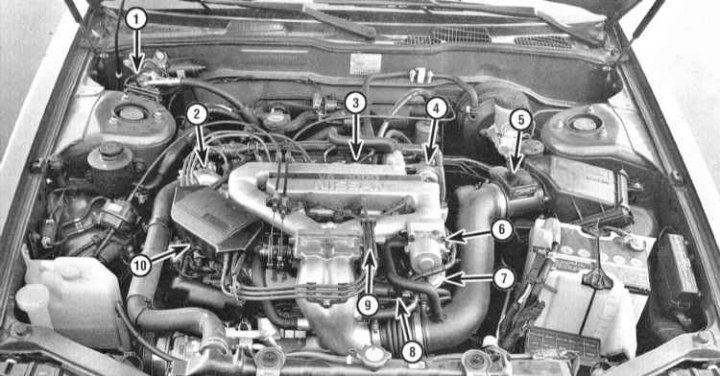
1 - PAS switch sensor; 2 - Engine coolant temperature sensor; 3 - PCV valve; 4 - Power valve actuator; 5 - MAF sensor; 6 - IAC valve; 7 - EGR valve; 8 - Knock sensor (under the exhaust manifold); 9 - TPS; 10 - Camshaft position sensor (in the ignition distributor)
Layout of engine management/emission control system components in the engine compartment for 1995 and later models.
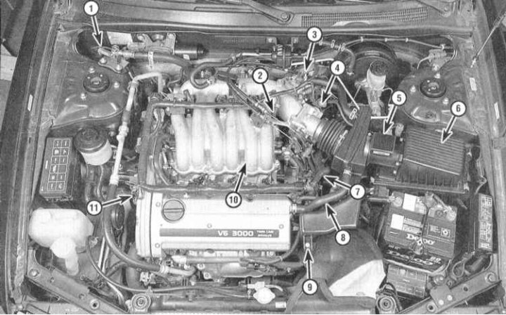
1 - PAS switch sensor; 2 - PCV valve; 3 - Fast Idle Speed Control Solenoids and IAC Valve; 4 - PS; 5 - MAF sensor; 6 - Intake air temperature sensor; 7 - EGR and EVAP control solenoid valves; 8 - Engine coolant temperature sensor; 9 - Location of MAP sensor; 10 - Knock sensor (under the intake manifold); 11 - Camshaft position sensor (in the ignition distributor)
In order to reduce the level of emissions into the atmosphere of toxic components that enter the composition of engine exhaust gases as a result of evaporation and incomplete combustion of fuel, as well as to maintain engine efficiency and reduce fuel consumption, the vehicles discussed in this Manual are equipped with a number of special systems that could be combined under the general name of engine management and exhaust toxicity reduction systems.
The systems related to engine management and exhaust gas toxicity control include the following:
- a) Electronic engine management system;
- b) Evaporative emission control system (EVAP);
- c) Positive Crankcase Ventilation (PCV) system;
- d) Exhaust gas recirculation (EGR) system;
- e) Catalytic converter.
The operation of all of the systems listed is, in one way or another, directly or indirectly, related to the control of reducing the toxicity of exhaust gases. The following Sections provide general descriptions of the operating principles of each of the systems, as well as procedures for diagnostic checks and repairs (if such seems possible) individual components, the execution of which is within the skill level of the average amateur mechanic.
Before concluding that any of the emission control systems has failed, carefully check the proper functioning of the fuel and ignition systems (see Chapters Power and exhaust systems and Engine electrical equipment). Diagnostics of some of the units of the toxicity reduction systems requires the use of special, difficult-to-use equipment and a certain qualification of the performer, and therefore, it would be reasonable to entrust its implementation to professional mechanics of a specialized service station.
The above does not mean that maintenance and repair of components of toxicity reduction systems in practice seem difficult to perform. Do not forget that one of the most common causes of failures is an elementary violation of the quality of vacuum or electrical connections, and therefore, first of all, you should always check the condition of the nipples and electrical connectors. The car owner can independently and quite easily perform a number of checks, as well as perform many routine maintenance procedures for most system components at home, using a standard set of adjustment and plumbing tools.
Note. Do not forget about the additional federal warranty obligations that fall under the components of the engine's toxicity reduction and control systems. Before proceeding with any repair procedures for components and parts of these systems, please consult the Nissan representative office about the conditions for compliance with these obligations.
Please take all precautions specified in the following Sections when servicing the electronic components of the systems in question. It should be noted that the illustrative material may not always exactly correspond to the actual placement of components on the vehicle. Such discrepancies are due to the ongoing modification process within the standard design of each model.
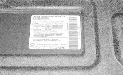
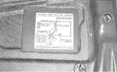
The Vehicle Emission Control Information Label (VECI) is located in the engine compartment of the vehicle. The label contains the necessary information on the settings and tests of the systems under control, taking into account all modifications made to the specific vehicle, as well as a diagram of the vacuum hose routing with identification of the various components. Before servicing the emission control and engine management systems, carefully read the VECI data.
Note: The hose routing diagram may be provided on a separate nameplate.
 |
 |