


Examination
Note: Performing the following procedure may cause a fault to be stored in the OBD memory and the Check Engine Light to be illuminated. Once the check and any necessary repairs have been completed, be sure to clear the system memory (see section On-Board Diagnostics (OBD) System - Operating Principle and Error Codes).
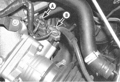
1. Before proceeding directly to the TPS test, make sure that the power supply from the PCM to the TPS is correct and there are no ground faults. Disconnect the electrical wiring from the TPS and connect the positive probe of the voltmeter to the green/black terminal (1993 and 1994)/red (since 1995) wire harness in the contact connector. Connect the negative probe to the terminal of the black wire. With the ignition on (do not start the engine) the device should register about 5.0 V. The absence of voltage indicates a break in the PCM circuit or failure of the module itself (in the latter case, the vehicle should be taken to a service station to perform diagnostics of the control module and perform appropriate repairs).
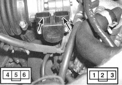
2. To check the proper functioning of the TPS, connect an ohmmeter to terminals #2 and #3 of the sensor. Measure the resistance of the TPS with the throttle fully closed, then begin to gradually open the throttle, observing the change in resistance of the sensor. On 1993 and 1994 models, the meter reading should change from 1.0 kOhm with the throttle fully closed to 9.0 kOhm with the throttle fully open. On 1995 and later models, from 0.5 kOhm to 4.0 kOhm, respectively. The increase in resistance should occur smoothly.
3. Disconnect the wiring from the throttle open/closed position switch. Connect an ohmmeter to terminals #5 and #6 of the sensor connector. Check for continuity at the switch with the throttle fully closed, then open the throttle slightly. There should be no continuity with the throttle open, otherwise replace the TPS assembly.
Replacement
1. Disconnect the negative cable from the battery.
Warning! If the car stereo system is equipped with a security code, make sure you have the correct combination to activate the system before disconnecting the battery!
2. Remove the air intake duct (see Chapter Power and exhaust systems) and disconnect the wiring from the TPS and the throttle position switch.
3. Remove the two mounting screws and remove the TPS assembly from the throttle body.
4. Install the new sensor in its original place and loosely screw in the mounting screws.
5. Perform TPS adjustment (see below), then tighten the fasteners completely.
Adjustment
1. Remove the air intake duct (see Chapter Power and exhaust systems).
2. Loosen the TPS assembly mounting screws on the throttle body.
3. On models equipped with a fully open/closed throttle position switch, disconnect the wiring from the switch and connect an ohmmeter as per the instructions in paragraph 4. Insert a 0.3 mm thick feeler gauge between the throttle lever and its stop screw - the device should register continuity. Now insert a 0.4 mm thick blade into the gap - this time the circuit should be open. Turn the TPS until the required result is achieved, then firmly tighten the mounting screws.
Attention! Do not touch the throttle lever stop screw under any circumstances - it is factory-set and cannot be adjusted!
4. On models without a throttle switch terminal sensor, use a voltmeter to probe the reverse ends of the white and black wire terminals on the TPS wiring harness connector (try not to damage the terminals when inserting the test leads-for more information, see the Chapter On-board electrical equipment). With the ignition on (do not start the engine) and with the throttle fully closed the instrument should register a reading in the range of approximately 0.4÷0.5 V, otherwise make the appropriate adjustment by rotating the TPS assembly, then tighten the mounting screws securely.