 |  |
Examination
Note. Performing the procedure described below may lead to the entry into the OBD memory of a malfunction, which will be highlighted by a control lamp "Check engine". Upon completion of the check and the corresponding remedial repair, do not forget to clear the system memory (see Section On-Board Diagnostic System (OBD) - the principle of operation and fault codes).
TFR sensor REF
Disconnect the sensor wiring connector and connect an ohmmeter to the contact terminals. At a temperature of 20°C, the required resistance is 470 ÷ 570 Ohm. A defective sensor must be replaced. If the measurement result meets the rated requirements, refer to the wiring diagrams (see chapter Onboard electrical equipment) and check the condition of the wiring in the section of the circuit between the sensor and the PCM. Check for signs of poor grounding on the black wire of the sensor wiring harness. If no irregularities can be identified, the car should be driven to a service station to diagnose the condition of the PCM and perform the appropriate refurbishment.
TFR POS sensor
1. Disconnect the wiring from the sensor. Turn on the ignition. check for battery voltage at the red wire terminal of the harness side connector. If there is no voltage, check the condition of the wiring in the section of the circuit between the ECCS relay and the battery (don't forget to check the condition of the fuses first). Check the condition of the ECCS relay and the wiring coming from it to the sensor (see wiring diagrams at the end of the Chapter Onboard electrical equipment). Check for a voltage of 5.0 V at the white wire terminal. If there is no voltage, check the condition of the circuit between the PCM and the sensor. With a good circuit, drive the vehicle to a service station to diagnose the condition of the PCM and perform the appropriate refurbishment. Also check for signs of poor grounding on the harness black wire.
2. Remove the sensor. Turn off the ignition and connect the wiring to the sensor. Connect the positive voltmeter lead to the black wire terminal on the back of the connector (see chapter for details Onboard electrical equipment). Ground the negative probe to ground. Turn on the ignition. Momentarily touch the sensor nose with a metal object (screwdriver type). At the moment of contact, the voltmeter should register a reading of 5.0 V. When the metal is withdrawn, the signal amplitude should quickly drop to zero. A defective sensor must be replaced. Note: In rare cases, the cause of entering a DTC may be a violation of the integrity of the ring gear of the flywheel / drive disk.
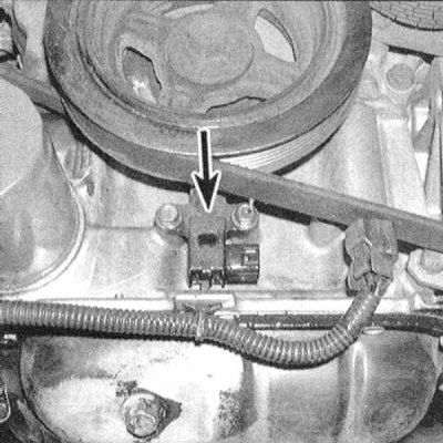
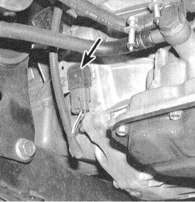
Replacement
1. Disconnect the wiring from the sensor.
2. Turn out a fixing bolt and remove the gauge. Installation is in the reverse order.