


Table of contents: Examination ↓ Replacement ↓
The VSS is mounted on the transmission case and is a variable magnetic resistance sensor. The sensor produces a sinusoidal AC signal whose frequency is proportional to the vehicle speed. The information received from the VSS is used by the PCM to control the duration of the fuel injector opening time and transmission shifting. In addition, the VSS is used as a speedometer drive. Failure of the sensor results in the recording of corresponding fault codes in the OBD memory.
Examination
Note: The correct functioning of the VSS can be verified by the adequacy of the speedometer readings.
1. Remove the VSS from the transmission case.
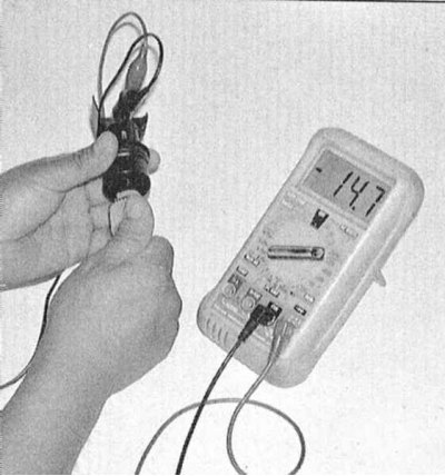
2. Connect the voltmeter to the two terminals of the sensor and switch the meter to the AC voltage measurement mode. Start manually rotating the sensor drive gear - the voltmeter should register a signal with an amplitude of about 0.5 V.
3. If there is no signal voltage, the sensor must be replaced.
4. If the above test results are positive, check for a break in the wiring in the circuit section between the VSS connector and the instrument panel (see the electrical connection diagrams at the end of Chapter On-board electrical equipment). If the wiring is OK, take the vehicle to a service station to have the PCM diagnosed and the appropriate repairs performed.
Replacement
1. Jack up the car and place it on supports.
2. Disconnect the electrical wiring from the speed sensor.
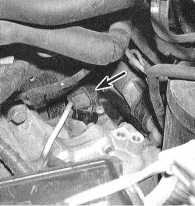
3. After removing the pinch bolt, loosen the clamp and remove the VSS from the transmission.
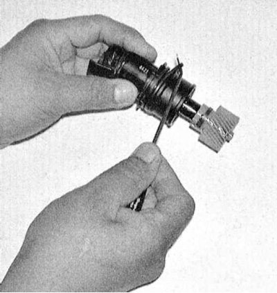
4. Check the condition of the sensor's sealing ring; replace if necessary.
5. Installation is carried out in reverse order.