


Table of contents: Models produced in 1993 and 1994. ↓ Models since 1995. ↓
Note: Performing the following procedure may cause a fault to be stored in the OBD memory and the Check Engine Light to be illuminated. Once the check and any necessary repairs have been completed, be sure to clear the system memory (see section On-Board Diagnostics (OBD) System - Operating Principle and Error Codes).
Models produced in 1993 and 1994.
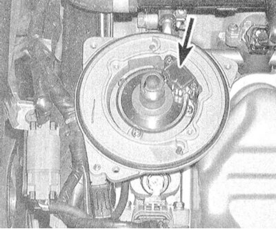
1. The CMP sensor is used to determine the engine speed and the current position of the pistons in its cylinders. The retrieved information is sent to the on-board processor, which, based on its analysis, makes the appropriate adjustments to the injection duration and ignition timing settings. The CMP sensor consists of a rotor plate and a wave signal-forming circuit. The rotor plate is divided into 360 divisions by grooves (with a step of 1°). The shape and location of the grooves allow tracking the engine speed and the current position of its camshaft. A set of light and photodiodes is built into the forming circuit. When the rotor teeth pass through the gap between the light and photo diode, a sequential interruption of the light beam occurs, which is then converted into a wave-like amplitude signal output to the PCM. The PCM sensor is built into the ignition distributor.
2. Disconnect the contact connector in the wiring harness going to the distributor. Turn on the ignition. Use a voltmeter to probe the terminal of the black and white wire of the connector. If there is no voltage, check the condition of the wiring in the section of the circuit between the ECCS relay and the battery. (don't forget about the fuses). Also check the condition of the relay itself and the wiring going from it to the distributor connector (see the electrical connection diagrams at the end of the Chapter On-board electrical equipment). Using an ohmmeter, check the proper grounding of the black wire terminal.
3. Turn off the ignition and remove the distributor from the engine (see Chapter Engine electrical equipment). Restore the original wiring connection. Connect the positive probe of the voltmeter to the terminal of the green-black wire on the back of the connector. Ground the negative probe to ground. Turn on the ignition and begin to slowly turn the distributor shaft, monitoring the meter readings. The following picture should take place: 6 jumps with an amplitude of 5.0 V per revolution of the shaft against the background of a zero base signal. This check confirms the correctness of the 120° signal registration.
4. With the ignition off, connect a voltmeter to the green-yellow wire terminal. Turn on the ignition and begin to slowly rotate the distributor shaft. This time, there should be regular 5-volt voltage surges with a frequency of 360 pcs. per shaft revolution. This procedure allows you to verify that the 1° signal is being generated properly.
5. If the results of the above checks are negative, the ignition distributor assembly must be replaced (see Chapter Engine electrical equipment), - the SMR sensor cannot be serviced individually.
(The article was copied from here: nissanbook.ru)
Models since 1995.
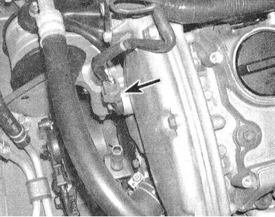
1. The CMP sensor is located in the timing cover in the front part of the power unit. The sensor consists of a permanent magnet, a core and a wire winding and is used to detect the grooves in the camshaft sprocket. When the sprocket teeth pass near the sensor, the surrounding magnetic field changes, which in turn is converted into a signal voltage sent to the PCM. Based on the analysis of the information received from the sensor, the control module determines the position of the pistons in their cylinders (TDC).
2. Disconnect the electrical wiring from the sensor. Using an ohmmeter, measure the resistance between the two terminals of the sensor connector. At a temperature of 20°C, the resistance should be 1440÷1760 Ohm (sensor manufactured by Hitachi)/2090÷2550 Ohm (sensor manufactured by Mitsubishi) the faulty sensor must be replaced.
3. If the above check is positive, refer to the electrical connection diagrams (see Chapter On-board electrical equipment) and check the wiring coming from the PCM for signs of breaks. Make sure there are no signs of a violation of the quality of the grounding of the black wire of the harness (use an ohmmeter). If the sensor and wiring are OK, take the vehicle to a service station to have the PCM diagnosed and repaired accordingly.