


Table of contents: Examination ↓ Replacement ↓
On models since 1996, the manifold absolute pressure sensor in combination with the MAP solenoid valve is used to monitor the depth of vacuum in the intake manifold. Changes in this parameter relative to barometric pressure are the result of changes in the current engine load and engine speed. The PCM uses the signals from the MAP sensor for diagnostic purposes. When the control module sends voltage to the MAP solenoid valve, the latter generates a vacuum signal that switches the MAP sensor to measure barometric pressure. In the absence of voltage on the valve, the MAP sensor reads the depth of vacuum in the manifold, any change in which is converted into a signal voltage, which is immediately transmitted to the PCM. The amplitude of the signal generated by the sensor can vary in the range from 0.5 V with the throttle valve fully closed, to 5.0 V with the throttle valve fully open (low vacuum depth). There is also a certain dependence of the amplitude of the signal generated by the sensor on the barometric pressure, determined by the altitude of the vehicle above sea level. The sensor and the electromagnetic valve MAP are installed on the rear (from the transmission side) end of the left (front) cylinder head. RCM distinguishes several types of sensor malfunctions, each of which OBD assigns an individual fault code.
Examination
Note: Performing the following procedure may cause a fault to be stored in the OBD memory and the Check Engine Light to be illuminated. Once the check and any necessary repairs have been completed, be sure to clear the system memory (see section On-Board Diagnostics (OBD) System - Operating Principle and Error Codes).
MAP sensor
1. Disconnect the vacuum hose from the MAP sensor and connect a vacuum gauge to the latter. Start the engine at idle speed - after about 5 seconds the gauge should register a vacuum, otherwise check the vacuum hose connecting the sensor to the electromagnetic valve for cracks and signs of obstruction. If the hose is OK, you should check the condition of the electromagnetic valve. If there is a vacuum, proceed to check the condition of the MAP sensor itself.
2. Disconnect the wiring from the MAP sensor. Connect a voltmeter to the terminals of the red () and black (-) wires on the connector. With the ignition on (do not start the engine) the meter should indicate 5.0 V, otherwise check the circuit condition between the connector and the PCM. If the wiring and connections are OK, the vehicle should be taken to a service station to have the control module diagnosed and repaired accordingly.
3. Turn off the ignition and connect the wiring to the sensor. Connect the positive probe of the fan to the terminal of the white wire on the back of the connector (for details, see Chapter On-board electrical equipment), ground the negative probe to ground. Turn on the ignition (do not start the engine), - the voltage must be in the range from 3.2 to 4.8 V.
4. Disconnect the vacuum hose from the sensor and connect a hand vacuum pump instead. Create a vacuum of about 203 mm Hg on the sensor. The amplitude of the signal voltage generated by the sensor should drop to 1.0÷1.4 V, otherwise replace the assembly.
Solenoid valve
1. Disconnect the intake manifold vacuum source hose from the MAP electromagnetic valve. Connect a vacuum gauge to the hose. Start the engine at idle speed - the gauge should register a vacuum, otherwise check the hose for cracks and signs of obstruction. If the hose is OK, proceed directly to checking the valve condition.
2. Disconnect the electrical wiring from the MAP solenoid valve and check for battery voltage between the two terminals of the connector with the ignition on (don't launch far). If there is no voltage, refer to the electrical connection diagrams (see Chapter On-board electrical equipment) and check the appropriate circuit for signs of open circuits between the fuse box and the valve connector (first of all, of course, you should check the condition of the fuses).
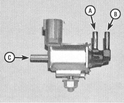
A - To the MAP sensor
B - To the air intake duct
C - To the source of vacuum in the intake manifold
3. If battery voltage is present, remove the solenoid valve and proceed to diagnose its condition outside the vehicle. Using a pair of fused jumper wires, connect the valve to a 12-volt power source. When voltage is applied, the valve should make a distinct click, accompanied by the opening of the air channel between the A and B fittings. If voltage is absent, the channel between the A and C fittings should open. A faulty valve must be replaced.
Replacement
1. Disconnect the negative cable from the battery.
Warning! If the car stereo system is equipped with a security code, make sure you have the correct combination to activate the system before disconnecting the battery!
2. Disconnect the electrical wiring from the sensor and/or the MAP solenoid valve.
3. Remove the screws securing the MAP sensor and/or solenoid valve. Disconnect the vacuum hose(s) and remove the corresponding assembly.
4. Installation is carried out in reverse order.