Examination
Note. Performing the procedure described below may lead to the entry into the OBD memory of a malfunction, which will be highlighted by a control lamp "Check engine". After completing the check and the corresponding remedial repair, do not forget to clear the system memory (see Section On-Board Diagnostic System (OBD) - the principle of operation and fault codes).
1. Before proceeding directly to assessing the condition of the sensor, make sure that the power supply to it from the PCM is working properly and that there are no signs of ground faults. Disconnect the wiring from the IAT sensor and connect a voltmeter to the two connector terminals on the harness side. Turn on the ignition (do not start the engine), - the meter should read 5.0 V, otherwise check the condition of the wiring in the section of the circuit between the sensor and the PCM. If the circuit is OK, drive the vehicle to a workshop to diagnose the condition of the PCM and perform the appropriate reconditioning.
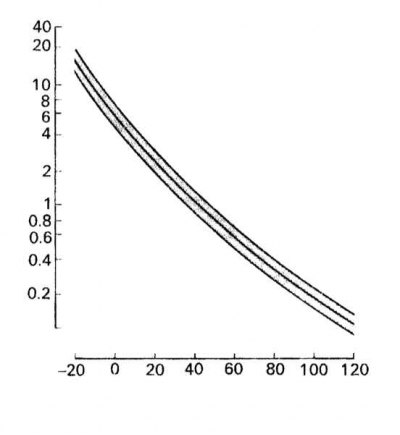
2. With the ignition off, disconnect the electrical wiring from the IAT sensor and use an ohmmeter to measure the resistance between the two terminals of the sensor connector when the engine is cold. Repair the original wiring, start the engine and warm it up to normal operating temperature. Disconnect the connector again and repeat the resistance measurement. Compare the results of the two measurements with the temperature plot of the sensor. A defective sensor must be replaced.
Note. A finer check of the IAT sensor condition can be done outside the vehicle and plotting a complete temperature dependence graph by immersing it in hot water.
Replacement
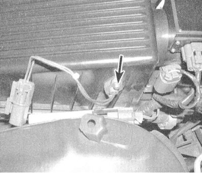
1. Disconnect the wiring from the IAT sensor.
2. Remove the sensor from the intake duct (take care not to damage the plastic components).
3. Installation is carried out in the reverse order.