Distributor
Checking the angle sensor
1. Remove the distributor from the engine.
2. Disconnect the negative wire to the battery and the wiring to the distributor.
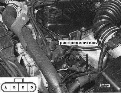
3. Using a voltmeter, probe terminal D of the electrical connector of the wiring harness (see insert in accompanying illustration).
4. Turn the ignition key to the ON position and, slowly rotating the distributor shaft by hand, check the voltage - it should fluctuate between 5 and 0 V.
5. Repeat the test for terminal C.
6. If the voltage does not meet the specified requirements, perform the following procedures:
- Remove the distributor cap and give the speed limiter. Remove the screen plate and slider from the distributor.
- Check the angle sensor signal plate for dust and damage. If necessary, gently wipe the plate and surrounding components. If the signal plate is damaged, the distributor must be replaced (You can't buy a new plate separately).
- If the distributor is in order, you should check the wiring of its power supply and grounding. If no obvious defects can be identified, the car should be driven to the dealership of the manufacturer for a detailed diagnosis.
Removal and installation
Attention! Withdrawal
1. Disconnect the electrical connector of the distributor and disconnect the ground wire from the distributor.
2. Disconnect the BB wire of the ignition coil from the distributor cover, remove the fixing screws and set the cover aside with the spark plug wires connected to it. Turn the engine clockwise so that the mark on the crankshaft pulley aligns with the zero mark on the timing cover, and the distributor slider turns towards the location of the BB terminal of the wire of the first cylinder in the distributor cover.
3. Mark the position of the distributor housing in relation to the cylinder head in order to simplify the initial setting of the ignition timing during assembly.
4. Give a fixing bolt and take the distributor from a head of cylinders.
Note. Do not allow engine cranking with the distributor removed.
Attention! Installation
Installation is in the reverse order.
1. Make sure the crankshaft pulley mark is still aligned with the zero mark on the front cover.
Note. If the crankshaft turned with the distributor removed, remove the spark plug of the first cylinder, plug the spark plug hole with your finger and ask an assistant to turn the crankshaft manually clockwise. When there is a noticeable feeling of pressure, turn the shaft a little more until the marks on the pulley and cover are aligned.
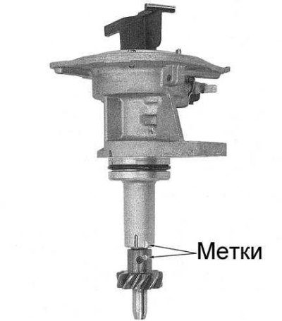
2. Make sure the mark on the distributor drive gear is aligned with the reciprocal mark in the form of a small risk on the distributor housing (see accompanying illustration) and insert the distributor into the cylinder head, also aligning the landing marks.
3. Screw in and firmly tighten the mounting bolt.
4. Install the distributor cap and tighten the fixing bolts.
5. Connect the electrical wiring to the distributor and the negative wire to the battery.
6. Check up correctness of installation of an advancing angle of ignition.
Removing and installing the air flow meter
Attention! Withdrawal
1. Disconnect the electrical wiring from the airflow meter.
2. Release a collar and disconnect a sleeve of an air duct from a measuring instrument of an air stream.
3. Release clips of fastening of the top half of the case of an air cleaner to bottom and remove assembly from the car.
4. Give fixing bolts and separate a measuring instrument of an air stream from the top half of the case of an air cleaner. Remove the holder plate from the inside of the top half of the air cleaner housing.
Attention! Installation
Installation is in the reverse order.
1. Ensure that the O-ring is properly seated in the recess in the airflow meter.
2. Track the correct placement of the filter element in the upper half of the air cleaner housing.
3. Start the engine and check for air leaks.
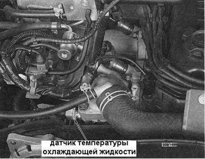
Coolant temperature sensor (CTS)
Examination
1. Remove CTS.
2. Connect an ohmmeter to the CTS terminals.
3. Dip the thermometer and the metal end of the sensor into a container of cold coolant. Make sure that the sensor and thermometer do not come into contact with the walls of the vessel (see accompanying illustration).
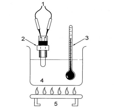
1 - to an ohmmeter; 2 - CTS; 3 - thermometer; 4 - vessel with coolant; 5 - heat source
4. Start gradually heating the coolant, monitoring the dependence of the sensor resistance on temperature. Compare your results with the normative data:
| Temperature,°С | Resistance, Ohm |
| 20°C | 2 100÷2 900 Ohm |
| 50°C | 680÷1000 Ohm |
| 80°С | 300÷330 Ohm |
5. If the above dependency is not met, the CTS must be replaced.
Removal and installation
Attention! Withdrawal
1. Disconnect wiring from CTS.
2. Drain the coolant from the cooling system, lowering its level below the level of the CTS.
3. Remove the gauge from the inlet pipeline.
Attention! Installation
1. Installation is carried out in the reverse order.
2. The sensor should be tightened securely, but not too tight.
3. Prime the cooling system.
Ignition coil
Examination
1. Disconnect the BB and simple wires from the coil.
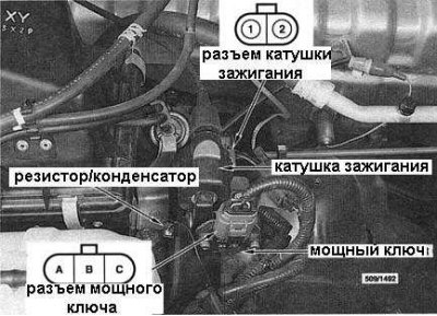
2. Using an ohmmeter, check the resistance between the coil terminals (see inserts in accompanying illustration - the illustration also shows the location of the ignition coil, power output stage switch and resistor/capacitor). The required values are shown in the table:
| Terminals | Resistance |
| Terminals 1 and 2 | 1 ohm |
| Terminal 1 and BB terminal | 10 kOhm |
3. If the measurement result does not correspond to the normative data, the coil must be replaced.
Removal and installation
Attention! Withdrawal
1. Disconnect the electrical connectors at the ignition coil and output stage power key.
2. Disconnect the BB wire from the ignition coil, disconnect the ground wire from the bracket.
3. Give bolts of fastening of an arm and remove assembly from the car.
Attention! Installation
Installation is in the reverse order.
Powerful output stage key
Examination
1. Disconnect the electrical wiring from the power key.
2. Check for continuity between the key terminals. Compare the measurement results with the requirements given in the table:
| Terminal | Ohmmeter | Conductivity |
| A | + | No |
| B | - | |
| A | - | Eat |
| B | + | |
| A | + | No |
| C | - | |
| A | - | Eat |
| C | + |
Removal and installation
Attention! Withdrawal
1. Remove the ignition coil.
2. Loosen the fixing screws and remove the powerful output stage key from the bracket.
Installation is in the reverse order.
Resistor/capacitor test
1. Using a small screwdriver, carefully pry the resistor/capacitor out of the wiring harness next to the ignition coil.
2. Using an ohmmeter, check the resistance between the terminals close to the mounting tabs. The resistance must be 2200 ohms, otherwise the resistor/capacitor must be replaced.
Control Solenoid Valves
Examination
1. Disconnect the wiring from the corresponding solenoid valve (The location of the fuel pressure regulator solenoid valve on pre-October 1994 models is shown in accompanying illustration A, the charcoal canister purge valve is shown in illustration B).
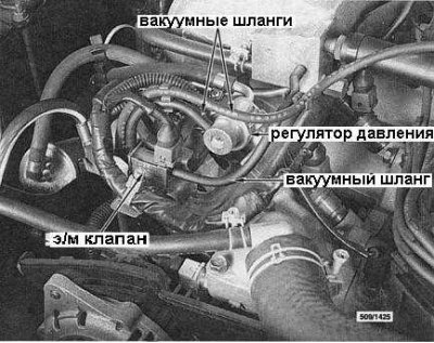
A.
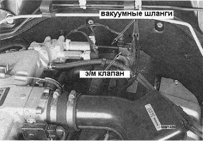
B.
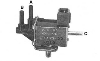
2. To check the valve:
- Apply a voltage of 12 V to it. Air between fittings B and A must pass, between fittings C and A - no (see accompanying illustration).
- Turn off the power. The picture should change to the opposite.
Removal and installation
Attention! Withdrawal
1. Disconnect from the corresponding valve electroconducting and vacuum hoses.
2. When removing the charcoal adsorber purge valve, loosen the valve bracket to the cylinder head cover and lift the bracket just enough to expose the valve mounting nut.
3. Give a fixing nut under an arm and remove the valve from the last.
Attention! Installation
Installation is in the reverse order. Make sure that the valve eye is correctly inserted into the bracket.
Throttle position sensor (TPS)
Examination
1. Disconnect the TPS electrical connector.
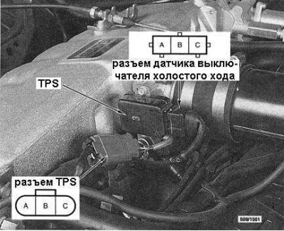
2. Connect an ohmmeter to terminals B and C of the sensor electrical connector (see accompanying illustration).
3. With the throttle closed, the resistance should be about 1,000 ohms.
4. With the damper partially open, the resistance should be between 1,000÷9,000 ohms.
5. At full throttle, the resistance should be about 9,000 ohms.
6. Disconnect the idle speed switch wiring plug from the TPS housing.
7. In accordance with these illustrations, connect an ohmmeter to terminals A and B of the idle speed switch.
8. With the throttle closed, there must be continuity between the terminals.
9. With a partially open damper, there should be no conductivity.
10. If measurements are not within specification, check TPS adjustment and if satisfactory results are not obtained, replace sensor.
Removal and installation
Attention! Withdrawal
1. Disconnect the idle speed switch wiring from the TPS housing, disconnect the TPS electrical connector.
2. Loosen the mounting screws and remove the TPS from the throttle body.
Attention! Installation
1. Installation is carried out in the reverse order.
2. Make sure the flat on the throttle shaft is properly aligned with the TPS.
3. Adjust TPS if necessary.
Adjustment
1. Disconnect wiring from auxiliary air valve (AAS).
2. Disconnect the idle speed switch wiring plug from the TPS housing.
3. Start the engine and warm it up to normal operating temperature.
4. In accordance with the data of Illustration 4.44, connect an ohmmeter between terminals A and B of the idle speed switch.
5. Loosen the fixing screws and adjust the TPS so that continuity occurs at engine speeds of 900±150 rpm and is absent above 1,050 rpm.
Note. If the desired result is not obtained, replace the TPS.
6. Tighten the mounting screws and check for proper adjustment.
7. Shut off the engine, disconnect the ohmmeter and connect the electrical wiring to the TPS and AAC valve.
Additional air valve (AAS)
Examination
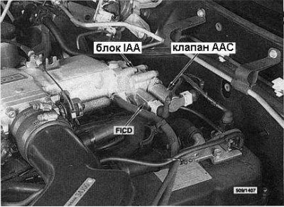
1. Disconnect the electrical wiring from the AAC valve (see accompanying illustration).
2. Measure the resistance between the valve terminals - it should be about 10 ohms, otherwise the valve must be replaced.
Removal and installation
1. Disconnect the electrical wiring and bypass air hose from the AAC valve.
2. Give fixing bolts and remove assembly of the valve from the block of adjustment of air of idling (IAA).
3. Give fixing bolts and remove the electromagnet coil from the AAC valve body.
4. Check the patency of the channels. Check that the plungers slide freely in the casing and that the springs are not broken or otherwise damaged. If necessary, remove carbon deposits from the channels with a soft cloth and carburetor cleaner.
Installation is in the reverse order. When installing the AAC valve, use a new gasket.
Fast idle speed compensation device (FICD)
Examination
1. Disconnect the electrical wiring from the FICD.
2. Apply 12 volts to the FICD solenoid terminals. When the voltage is applied, a distinct click should be heard, otherwise replace the FICD
Removal and installation
1. Disconnect wiring from FICD valve.
2. Removing the FICD from the IAA valve.
3. Remove the plunger and spring from the valve. Check that the plug slides freely in the valve and that the spring is not broken or otherwise damaged. If necessary, remove carbon deposits from the channels with a soft cloth and carburetor cleaner.
Installation is in the reverse order.
1. Check the condition of the sealing washer, replace if necessary.
2. Track correctness of installation of a spring on a plunger.
Removal and installation of the block of adjustment of air of idling (IAA)
1. Remove the AAC valve.
2. Using a suitable bar wrench, loosen the mounting bolts and remove the IAA block with gasket from the air path pressure chamber.
3. If necessary, turn the FICD out of the block.
Installation is in the reverse order. Use a new gasket when installing the AAC valve and IAA block.
Air regulator
Note. The air control valve is located under the intake manifold, near the dipstick.
Examination
1. Disconnect the electrical wiring from the air regulator.
2. Check the resistance between the regulator terminals. It should be about 70÷80 Ohm, otherwise replace the regulator.
Removal and installation
1. Disconnect the electrical wiring from the air regulator.
2. Loosen the clamps and disconnect the hoses from the regulator.
3. Give fixing bolts and remove a regulator from the inlet pipeline.
Installation is in the reverse order.
Power steering oil pressure switch
Examination
1. Disconnect the electrical wiring from the sensor-switch on the steering pump.
2. Connect an ohmmeter to the sensor-switch terminals and start the engine.
3. When the engine is idling and the front wheels of the vehicle are in a straight position, the sensor-switch must be open (no conductivity).
4. With the engine running at idle and the front wheels turned to either side, the sensor must be closed (there is conduction).
5. If the test conditions are not met, the power steering oil pressure switch should be replaced.
Removal and installation
1. Disconnect the electrical wiring from the sensor-switch.
2. Remove the gauge switch from the steering pump.
Installation is in the reverse order. Check that the fluid level in the power steering reservoir is correct.
Relay
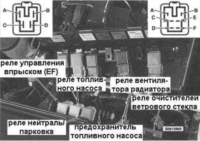
Note. The procedures below apply to the engine management system relay (ECCS), fuel pump and Park/Neutral (start enable switch), located near the battery (see accompanying illustration).
Examination
1. Remove the relay from the housing in the engine compartment.
2. Apply 12 V to terminals A and B and check for continuity between terminals C and D (see illustration). on models with a 6-terminal fuel pump relay, check continuity between terminals E and F (it must take place).
3. There must be no continuity between terminals C and D, or E and F, when voltage is not applied to terminals A and B.
4. If this check does not give the required results, replace the relay.