General information
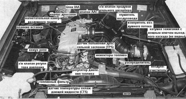
The accompanying illustration shows a view of the 4.2L EFI engine compartment showing the location of the various power and engine control components.
Starting in October 1994, manufacturers have discontinued the use of the pressure regulator solenoid valve.
The engine management system is referred to as the electronic ignition control system in this manual (ECCS). The system controls the ignition and fuel injection simultaneously.
The central component of the ECCS is the control unit (ECU), which is a microprocessor. The ECU controls the ignition timing and fuel injection amount based on signals it receives from various sensors. By detecting changes in engine load, RPM, vehicle speed, coolant temperature, throttle position, gear selection, intake air temperature, and exhaust gas composition, the ECU issues commands to appropriately adjust the ignition timing and fuel injector opening times in order to obtain maximum engine performance under current conditions.
When registering a repetitive abnormal signal, the ECU remembers the circuit of the signal source and writes it to the memory unit in the form of a digital code, which greatly simplifies the procedure for diagnosing system malfunctions. If a malfunction of the distributor angle sensor or a global internal failure within the ECU that affects the efficiency of the engine is detected, the warning lamp turns on "Check engine" on the instrument panel, at the same time with which the ECU activates the emergency operation system, which allows you to continue operating the vehicle with limited engine capabilities until the cause of the failure is eliminated. Reading fault codes from the ECU memory in the workshop of the dealership of the car manufacturer will facilitate the diagnosis of the causes of the failure.
The high-energy ignition system consists of a distributor, a powerful output stage key, an ignition coil and an electrical connection.
The distributor performs a dual function. First, it supplies secondary coil voltage to the spark plugs. Secondly, the distributor supplies the ECU with information about engine speed and piston position. This information is taken by the rotation angle sensor located inside the distributor.
Since the engine management system is responsible for setting the ignition timing, the distributor is not equipped with either vacuum or centrifugal ignition timing correctors.
The powerful key of the output stage is fixed near the ignition coil. And it performs the function of interrupting the primary circuit, turning on at the command of the ECU. In this case, a high voltage is induced in the secondary circuit.
The ignition coil is specially designed to meet the special requirements of the electronic ignition system and should only be replaced with a similar one.
The engine is powered by an electronic multi-position fuel injection system. The system injects fuel into the intake air stream at the intake ports of the cylinder head. Next, the air-fuel mixture is fed into the combustion chambers through the intake valves.
The fuel supply to the injectors is provided by a high-pressure submersible pump mounted in the fuel tank. In order to suppress fuel pulsations caused by the operation of the injectors and its own functioning, the pump is equipped with a special damper.
The pressure in the supply system is maintained at the level of 235÷294 kPa, depending on the pressure in the pipeline. The fuel pressure is controlled by a special regulator mounted in the fuel line. When the engine is not running, the fuel in the area between the injectors and the fuel pump remains under pressure due to the installation of a one-way valve in the pump.
The amount of injected fuel is determined by the opening time of the injectors. The duration of the injector opening interval is determined by the ECU based on data received from the distributor angle sensor and the airflow meter. The base injection duration can then be adjusted based on information from the coolant temperature sensor (CTS), throttle and start enable sensors, vehicle speed sensor, ignition key position and l-probe data in order to get the most out of the engine in specific conditions and the current mode of operation.
The air regulator provides an increase in engine idle speed during its warm-up by bypassing the air flow around the throttle. The operation of the air regulator is controlled by a bimetallic plate, which bends when heated by electric current. Bending, the bimetallic spring rotates the disk inside the air regulator, which leads to a gradual reduction in air flow until it is completely blocked.
Idle Air Control Unit (IAA), mounted at the rear of the air path pressure chamber, controls the engine idle speed. The unit is equipped with a speed adjustment screw, an auxiliary air valve and a fast idle speed compensation device (FICD).
The AAC valve provides additional air to bypass the throttle, thereby maintaining idle speed as engine loads increase. The FICD operates similarly to the AAC valve, but is specifically designed to compensate for the increase in load associated with turning on the air conditioner.
The throttle body is located on the pressure chamber of the air path and controls the amount of air sucked into the engine depending on the position of the gas pedal.
The effectiveness of the engine management system depends on the accuracy of the information supplied to the ECU about the amount of air flow controlled from the air flow meter. The cleanliness, quality of condition and security of all air, fuel and electrical connections are therefore of particular importance.