


Table of contents: Removal ↓ Installation ↓ Disassembly ↓ Servicing of carburetor top cover…↓ Maintenance of main building units ↓ Maintenance of throttle body…↓ Assembling the carburetor ↓ Checks and adjustments ↓
Removal
1. Disconnect the negative cable from the battery.
2. Remove the air cleaner assembly from the carburetor.
3. Disconnect the fuel supply hose from the carburetor and plug it to prevent dirt from entering the fuel system.
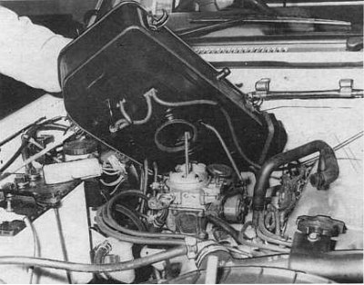
4. Mark and disconnect the vacuum hoses from the carburetor (in the accompanying illustration, the air purifier is raised to show the vacuum connections (4.2L engine)).
5. Disconnect the carburetor electrical connectors.
6. Using the drive lever, move the throttle valve to the fully open position and, using the resulting slack in the drive cable, disconnect the latter from the throttle lever.
7. Loosen the nuts securing the carburetor to the intake manifold, remove the washers. Remove the carburetor with the gasket. Discard the gasket.
8. On 3.0L models, disconnect the electrical connector and remove the heater.
9. Plug the intake manifold inlet with a clean, lint-free cloth to prevent foreign objects from entering the engine.
Installation
Installation is carried out in reverse order.
1. Be sure to install a new gasket between the carburetor and the intake manifold. If necessary, carefully remove any traces of the old gasket from the mating surfaces beforehand, making sure that no debris falls into the intake manifold.
2. Check the carburetor for signs of fuel leaks and vacuum losses. After the engine has warmed up, adjust the idle speed.
Disassembly
External view of the 4.2L engine carburetor showing the location of the various components (side view and top view - carburetor model with manual transmission)
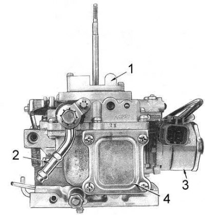
1 - air ventilation; 2 - fuel inlet pipe; 3 - Assembly of the mixture quality control device during deceleration (BCDD); 4 - side cover
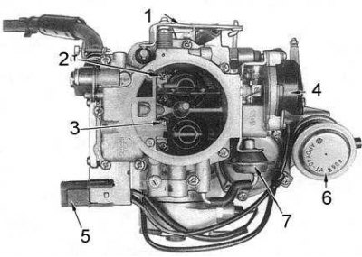
1 - accelerator pump drive lever; 2 - primary diffuser; 3 - secondary diffuser; 4 - automatic start device; 5 - electrical connector; 6 - actuator for switching on fast idle speed; 7 - Automatic starter air damper opener
When performing a major overhaul of the carburetor, you should pay attention to the following points:
- All components should be thoroughly washed in a suitable solvent and inspected for signs of wear and damage;
Note: Do not immerse electromagnetic assemblies and components with vacuum diaphragms in solvent
- Try to store all components removed from the carburetor separately and in relation to their position in the assembly;
- Use only compressed air to clean various jets, throttles and channels. Under no circumstances should blockages be removed using wire or other types of probes!
- When performing a major overhaul of the carburetor, use special gasket repair kits and be sure to replace all removed diaphragms and sealing rings. Also replace all worn components.
- To avoid damaging the jets and screw heads, use only the correct size screwdrivers and wrenches when removing/installing them.
1. Remove the carburetor from the vehicle.
2. Disconnect the throttle return springs from the accelerator pump drive lever.
3. Remove the E-clip and washer securing the accelerator pump drive lever to the carburetor top cover (the main components of the carburetor are shown in the accompanying illustration).
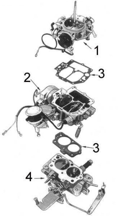
1 - top cover; 2 - main building; 3 - gasket; 4 - throttle body
4. Remove the fast idle cam E-clip, then hold the cam and disconnect the return spring.
5. Release the locking tab on each wire in the carburetor electrical connector. Try to remember the position of the wires in the connector.
6. Disconnect the return spring of the air damper opener of the automatic starting system from the automatic starting system assembly.
7. Loosen the mounting screws and partially separate the top cover from the main body of the carburetor. Disconnect the air damper drive lever from the latter's pivot axis.
8. Remove the top cover with gasket from the main body of the carburetor.
9. Remove the accelerator pump spring from the main body.
10. If installed, remove the plastic flow meter reduction tube located above the idle jet II.
11. Turn the main body upside down and remove the E-clip and throttle diaphragm actuator rod II.
12. Loosen the mounting screws at the bottom of the throttle body. Note the location of the hollow screw.
13. Remove the main body with the gasket from the throttle body. Remove the insulator from the body.
14. Now the carburetor will be disassembled into three main units - the top cover, the main body and the throttle body.
15. Servicing the carburetor top cover assemblies
16. Remove the fuel inlet hollow bolt retaining plate.
17. Unscrew the hollow bolt, remove the fuel inlet pipe, washers and filter. Check the condition of the filter, clean it if necessary or replace it.
18. Remove the accelerator pump plunger assembly. Inspect the plunger for signs of wear or damage. Replace the plunger if necessary.
19. If the kit is equipped accordingly, loosen the mounting screws and remove the plastic ventilation assembly with the gasket from the top cover.
20. Using pincers, remove the float pivot pin from the top cover, then remove the float and needle valve.
21. Using a screwdriver, remove the needle valve seat with washer from the top cover.
22. Remove the spring clip securing the needle to the float. Check the needle valve components for signs of wear, replace any defective ones.
23. Check the top cover for cracks and other damage. Make sure that the air flap of the automatic starter moves freely, without jerking or jamming points.
24. On 3.0L models, ensure that the idle lean mixture control bimetallic strip is not broken or otherwise damaged when the engine is warm.
25. Assemble in reverse order.
Servicing of carburetor top cover assemblies
1. Remove the fuel inlet hollow bolt retaining plate (the components of the carburetor top cover are shown in the accompanying illustration).
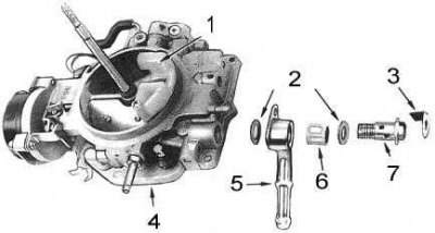
1 - ventilation assembly; 2 - washers; 3 - locking plate; 4 - top cover; 5 - tube; 6 - filter; 7 - hollow bolt
2. Unscrew the hollow bolt, remove the fuel inlet pipe, washers and filter. Check the condition of the filter, clean it if necessary or replace it.
3. Remove the accelerator pump plunger assembly. Inspect the plunger for signs of wear or damage. Replace the plunger if necessary.
4. If the kit is equipped accordingly, loosen the mounting screws and remove the plastic ventilation assembly with the gasket from the top cover.
5. Using a pair of pincers, remove the float pivot pin from the top cover, then remove the float and needle valve.
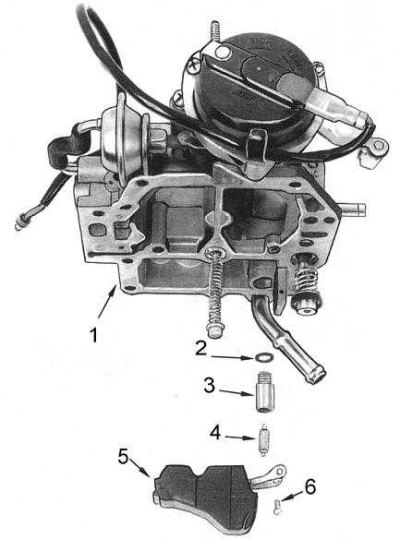
1 - top cover; 2 - washer; 3 - needle valve seat; 4 - float; 5 - needle; 6 - axial finger
6. Using a screwdriver, remove the needle valve seat with washer from the top cover.
7. Remove the spring clip securing the needle to the float. Check the needle valve components for signs of wear, replace any defective ones.
8. Check the top cover for cracks and other damage. Make sure that the air flap of the automatic starter moves freely, without jerking or jamming points.
9. On 3.0L models, ensure that the idle lean mixture control bimetal strip is not broken or otherwise damaged when the engine is warm.
10. Assemble in reverse order.
Maintenance of main building units
1. Remove the electromagnetic shut-off valve with the washer from the main body. Using a 12 V battery, check the valve for proper operation by pressing its body to the negative terminal of the battery and connecting the wire to the positive terminal. The valve plunger should retract. Replace the valve if necessary.
2. If equipped, remove the fuel-fuel mixture deceleration control solenoid (BCDD) with washer from the BCDD assembly.
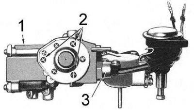
1 - main building; 2 - BCDD assembly mounting screws; 3 - electromagnet
3. Loosen the mounting screws and remove the BCDD assembly from the carburetor main body.
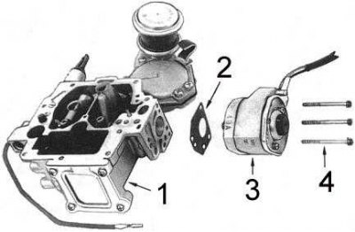
1 - main building; 2 - gasket; 3 - BCDD assembly; 4 - screws
4. Loosen the mounting screws and remove the fuel chamber side cover, gasket, and plug plate from the main body (or a viewing glass) and seal (see accompanying illustration).
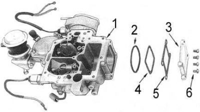
1 - main building; 2 - seal; 3 - lid; 4 - plate; 5 - gasket; 6 - screws
5. If equipped, loosen the mounting screws and remove the fast idle damper.
6. Loosen the mounting screws and remove the throttle body assembly II from the main body.
7. Remove the spring clip from the accelerator pump plunger well. Turn the main body upside down and remove the mesh screen and ball (see accompanying illustration).
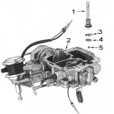
1 - plunger; 2 - main building; 3 - clamp; 4 - mesh screen; 5 - ball
8. Remove the accelerator pump discharge weight fixing plug, turn over the main body and remove the weight, spring and ball (see accompanying illustration).
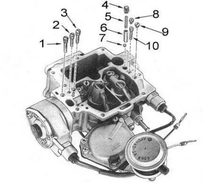
1 - Idle air jet II; 2 - idle fuel jet II; 3 - plug; 4 - cork; 5 - spring; 6 - weight; 7 - ball; 8 - screw; 9 - Idle air jet I; 10 - Idle fuel jet I
9. Remove the main air jets. Loosen the mounting screws and remove the nozzles from the main body. The removed components are shown in the accompanying illustration.
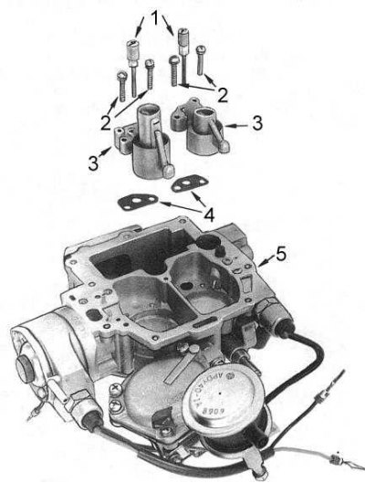
1 - main air jets with emulsion tubes; 2 - screws; 3 - sprayer; 4 - gaskets; 5 - main building
10. Remove the remaining jets from the main body.
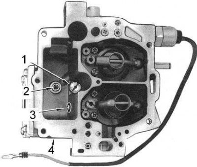
1 - economizer jet; 2 - main fuel jet I; 3 - main fuel jet II; 4 - main building
Note: It is important that the jets are installed correctly during assembly. Otherwise, problems with the engine operation will inevitably occur. If necessary, refer to the jet dimensions (see size and adjustment tables at the end of the Guide).
11. Thoroughly rinse each jet in a suitable solvent, then blow it out with compressed air.
Caution: To avoid causing damage, do not attempt to clean the jets with wire or thin drills under any circumstances.
12. Thoroughly wash the main body of the carburetor with solvent and dry it with compressed air.
13. Using a hand vacuum pump, check the throttle diaphragm II for proper operation. Replace any defective components.
Maintenance of throttle body components
Note: Due to the tolerances accepted by manufacturers, the probability of correctly reproducing the fit of the throttle shafts in the throttle body is extremely low. For this reason, if the shafts are damaged, the throttle body assembly must be replaced.
1. On models with automatic transmission, loosen the mounting bolts and remove the throttle switch sensor from the throttle body.
2. Wash the throttle body in a suitable solvent and dry it with compressed air.
3. Check the throttle actuator rods for signs of jamming; lubricate the actuator if necessary.
4. On models with AT, install the throttle switch sensor in its place on the throttle body, then adjust it.
Assembling the carburetor
Assembly is carried out in the reverse order of dismantling.
1. Using new gaskets, connect the throttle body to the main body of the carburetor. Tighten the mounting bolts securely. Make sure that the hollow screw is screwed into its original place in the throttle body (see accompanying illustration).
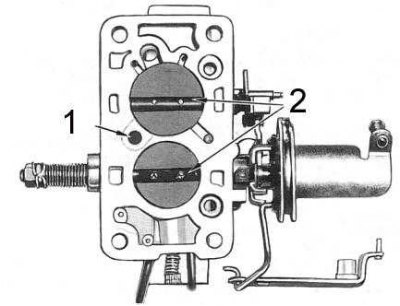
1 - hollow screw
2 - throttle valves
2. Install the throttle diaphragm II and secure it with the E-clamp.
3. Install the accelerator pump plunger assembly into its well. Be sure to replace the carburetor top cover gasket.
4. Install the top cover on the main body and connect the air damper drive lever to the rotary shaft of the latter. Tighten the fastening screws securely.
5. Install the fast idle cam with spring, put the E-clamp on the axle.
6. Install the accelerator pump drive lever axle bushing and connect the lever to the axle. Place the E-clamp on the axle and connect the throttle return springs.
7. Connect the throttle return spring II to the automatic starting assembly.
8. Connect the wires to the carburetor electrical connector, each in its original place.
9. Install the carburetor onto the intake manifold.
10. Adjust idle speed and fast idle speed if necessary.
Checks and adjustments
Adjusting the fuel level in the float
Note: On some models, the carburetor is equipped with a special inspection window. If the fuel level in the inspection window was normal before removing and disassembling the carburetor, and the needle and needle valve seat were not replaced during the maintenance procedures, no additional adjustment is required.
1. Remove the top cover with gasket from the carburetor.
2. Turn the top cover over so that the float seat tongue rests against the needle valve.
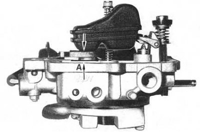
3. Measure the distance A (see accompanying illustration) from the top of the float to the gasket surface of the carburetor top cover. On 4.2 L models it should be 9.5÷10.5 mm, on 3.0 L models - 5.0÷6.0 mm.
4. If adjustments are necessary, carefully bend the float seat tongue to achieve the desired value. Make sure that the needle valve fits smoothly onto the float tongue.
5. Turn the top cover back to its normal position, allowing the float stop tab to come into contact with the stop.
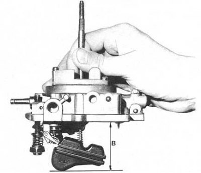
6. Measure the distance B (see accompanying illustration) from the gasket surface of the carburetor top cover to the bottom of the float. On 4.2 L models the result should be 47.5÷48.5 mm, on 3.0 L models - 44.0÷45.0 mm.
7. To make the adjustment, carefully bend the locking tab.
8. Install the top cover on the carburetor, start the engine and check it for vacuum losses and fuel leaks.
Adjusting fast idle speed without removing the carburetor from the engine
1. Start the engine and warm it up to normal operating temperature. In accordance with the manufacturer's instructions, connect the tachometer and set the idle speed and mixture quality. Stop the engine.
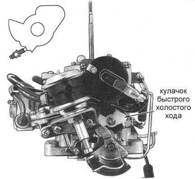
2. Open the throttle valve and set the adjusting screw to the second stage of the fast idle cam (see accompanying illustration - inset shows screw installed on second stage cam).
3. Without touching the gas pedal, start the engine and compare the tachometer readings with the standard requirements (see size and adjustment tables at the end of the Guide).
4. If adjustment is necessary, loosen the fast idle adjustment screw lock nut and turn the screw until the desired reading is achieved.
Adjusting the fast idle speed with the carburetor removed from the engine
1. Open the throttle valve and set the adjusting screw to the second stage of the fast idle cam.
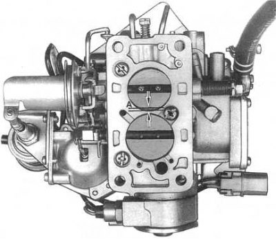
2. Measure the gap A (see accompanying illustration) between the throttle valve I and the inner wall of the carburetor. Compare the measurement result with the data size and adjustment tables.
3. To make the adjustment, loosen the fast idle adjustment screw lock nut and turn the screw until the desired reading is achieved.
Adjusting the vacuum drive for opening the air damper
1. Make sure that the choke valve is completely closed when the engine is cold.
2. Create a vacuum on the air damper opener and slightly push the piston rod towards the opener diaphragm.
3. Measure the gap between the edge of the air damper and the inner wall of the primary chamber. Compare the result with the requirements size and adjustment tables.
4. To make the adjustment, slightly bend the rod on the axle.
Adjusting the throttle damper
1. Start the engine and warm it up to normal operating temperature. Connect the tachometer and set the idle speed and mixture quality.
2. Open the throttle valve and check the engine speed when the damper contacts the adjusting screw. Compare the measurement result with the requirements size and adjustment tables.
3. If adjustments are necessary, turn the adjusting screw at the end of the damper shaft in the required direction and repeat the check in the previous paragraph.
4. Make sure the RPM drops smoothly from 2,000 to 1,000 RPM in about three seconds.
Adjusting the idle speed with the air conditioner on
1. Start the engine and warm it up to normal operating temperature. Connect the tachometer and set the idle speed and mixture quality.
2. Turn on the air conditioner and check the idle speed. Compare the result with the data size and adjustment tables.
3. To make adjustments on models with AT and 3.0 L, turn the adjusting screw on the end of the damper in the appropriate direction. On 4.2 L models with manual transmission, adjustment is made by turning the screw on the end of the throttle shaft.
Adjusting idle speed and mixture quality
The procedure is described in detail in Chapter Settings and ongoing maintenance.
Checking the correct functioning of the automatic starter
1. With the engine cold, open the throttle fully and make sure the air damper is closed. Make sure that the timing marks on the starter cover and the carburetor body are aligned.
Note: If the choke valve does not close, check the choke valve shaft for signs of sticking.
2. Start the engine and warm it up to normal operating temperature. Make sure the choke is fully open.
3. If the damper does not open completely, connect a test lamp between the wire on the power supply housing of the automatic starter and the nearest reliably grounded point. If there is no current (the lamp is not on), check the condition of the relay and wiring of the automatic starter.
Checking the proper functioning of the electromagnetic shut-off valve
1. Disconnect the carburetor electrical connector.
2. Apply battery voltage to the terminals shown in the accompanying illustration. When applying and disconnecting power, the valve should clearly click into place.
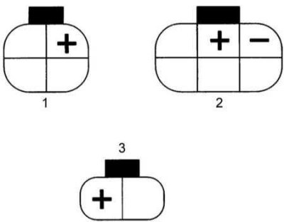
1 - 4.2 l manual transmission
2 - 3.0 l
3 - 4.2 l AT
3. Otherwise, replace the valve.
Adjusting the Throttle Position Sensor Switch (only models with AT)
1. Check the correct setting of the idle speed with the engine warmed up to normal operating temperature. Turn off the engine.
2. Disconnect the wiring from the throttle switch sensor and the throttle position sensor.
3. Start the engine and check the idle speed with the selector lever in the "N" position.
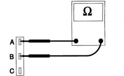
4. Check for continuity between terminals A and B (see accompanying illustration).
5. Make sure that the sensor-switch contacts open when the idle speed is exceeded by 250±150 rpm in the transmission position "N".
6. If adjustments are necessary, loosen the sensor-switch mounting bolts and rotate the latter until the contacts open at the desired moment (at the agreed speed).
7. Tighten the sensor-switch mounting bolts and check that the adjustment is correct.
8. Connect the wiring to the throttle switch sensor and the throttle position sensor.