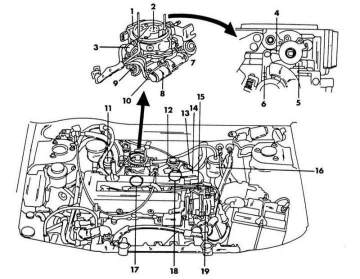
Location of individual elements of injection and ignition systems in the engine compartment of a car with an SR20Di engine
1 - air flow meter; 2 - central injection valve; 3 - fuel pressure regulator; 4 - fast idle cam; 5 - thermoelement; 6 - cam lever; 7 - throttle damper; 8 - additional air valve; 9 - throttle position sensor; 10 - switching valve for idle control; 11 - control valve; 12 - exhaust gas return valve; 13 - exhaust gas pressure control valve; 14 - activated carbon adsorber control valve; 15 - ignition coil; 16 - fuel filter; 17 - knock sensor; 18 - transistor; 19 - crankshaft angle sensor
1. crank angle sensor (19) performs the same task as described in p. "Open the lid...". The same applies to air flow meter (14) (see Section Multi-position injection system (SR20DE engine)).
2. Engine temperature sensor not visible in the illustration, it is located behind the oil filter in the location indicated in the illustration below. The sensor monitors the temperature of the coolant and provides information in the form of a signal to the electronic control device. The sensor is equipped with a thermistor that reacts to temperature changes. The electrical resistance of the thermistor decreases as the temperature rises.
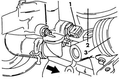
Coolant Temperature Sensor Position
1 - temperature sensor; 2 - intake manifold; 3 - oil filter
3. Throttle position sensor (9) has the same task as described in Section Multi-position injection system (SR20DE engine).
4. injection valve (injector) (2) (see Section Multi-position injection system (SR20DE engine)).
5. When the electronic control device sends a signal to the injector, the coil in the valve pulls the ball valve back and fuel is injected through the nozzle to the throttle valve. The duration of the injection is also determined by the control device.
6. pressure regulator (3) maintains a constant pressure of 2.5-2.55 bar. Since the amount of injected fuel depends on the duration of the injection, the pressure must be maintained at the named level.
7. Transistor (18) serves the same purpose (see Section Multi-position injection system (SR20DE engine)).
8. Fast idle cam (4) is located on the throttle body and provides sufficient RPM while the engine is cold. The cam is controlled by a thermocouple (5), which is filled with wax, which, under the influence of temperature, can expand and contract, while moving the lever (6).
9. In 8 position (8) located auxiliary air valve, which is switched off and on by the control device in order to supply the required air.
10. The mixture preheater is installed between the lower throttle body and the intake manifold and is located in the location indicated in the illustration below. The device is actuated by the control device and helps to atomize the fuel when the engine is cold.
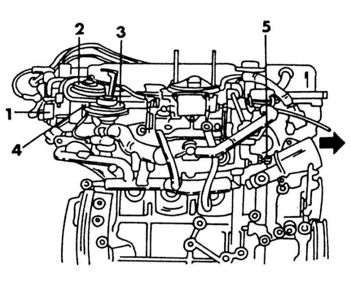
The position of some elements on the other side of the engine (which are not visible on figure). Arrow indicates forward direction
1 - control valve for exhaust gas return and activated carbon adsorber; 2 - exhaust gas pressure control valve; 3 - control valve for exhaust gas return; 4 - transistor; 5 - coolant temperature sensor
11. The speed sensor is installed in the speedometer and converts the readings of the device into pulses to report information to the control device. In order to maintain a constant speed when the engine is subjected to additional load due to the activation of the servo control, a oil pressure sensor (see Section Multi-position injection system (SR20DE engine)).
12. On the cylinder block is located engine knock sensor. When the engine starts to vibrate due to detonation, the vibration is converted by the sensor into a voltage signal, which is applied to the control device.
13. Fuel filter (16) is in a metal case to withstand the high pressure of the fuel. One hose is connected to the top and bottom of the filter. The filter sits in a spring latch. Before changing the filter (recommended every 40,000 km or every 2 years), reduce the pressure in the system to avoid fuel splashing. Install only the appropriate Specifications filter.
14. activated carbon adsorber serves for the same as on a carburetor engine (Chapter Multi-position injection system (SR20DE engine)).
15. Fuel pump located in the fuel tank (Chapter Multi-position injection system (SR20DE engine)).
All instructions regarding the ignition system are in Chapter Engine electrical system. On vehicles with a catalytic converter, a lambda probe is installed in the exhaust system. It measures the oxygen in the exhaust gases and adjusts the fuel-to-air ratio accordingly.
The injection system works together with the exhaust gas return system. The exhaust gas return control valve controls the amount of exhaust gases that are returned to the intake manifold. The valve, under the influence of vacuum under the throttle valve, closes or opens the exhaust gas supply to the intake manifold.