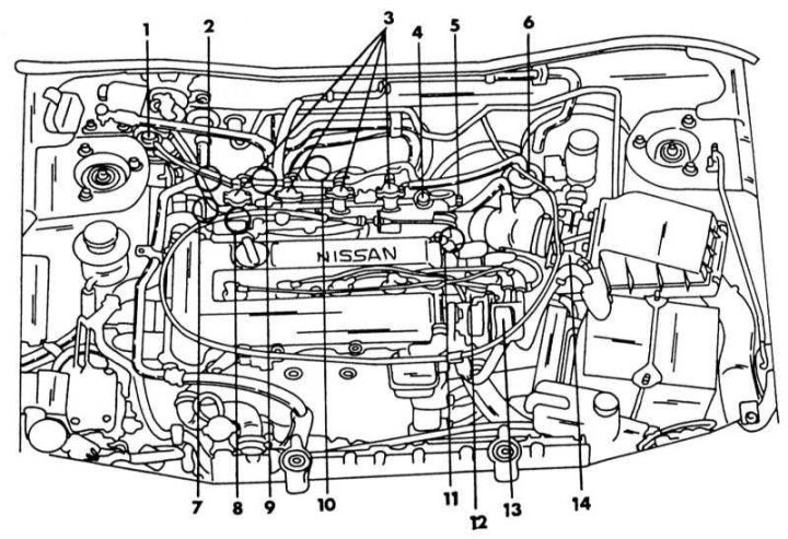
The position of individual elements of the fuel injection system and the ignition system in the engine compartment of a car with an SR20DE engine
1 - adsorber; 2 - additional air valve; 3 - injection valves; 4 - fuel pressure regulator; 5 - throttle position sensor; 6 - fuel filter; 7 - switching valve, idle adjustment; 8 - coolant temperature sensor; 9 - air regulator; 10 - resistor; 11 - transistor; 12 - ignition coil; 13 - crankshaft angle sensor; 14 - air flow meter
If you open the hood, you can see a lot of hoses, wires, and other parts common to a modern car, which are either related to the injection system or the ignition system. The illustration above is a view of the engine compartment, showing the location of the main elements of both systems. Let's briefly dwell on the work of some elements. crank angle sensor (13) installed in the ignition distributor and is the main element of both systems. The sensor monitors the engine speed and piston position and sends the appropriate signal to the control unit to control injection, ignition and other functions. The sensor has a rotor disk and a current circuit. The disc has 360 splines, each of which corresponds to a rotation of the crankshaft by 1°, as well as 4 other splines that serve for 4 cylinders and are located at a distance of 180°. Light and photocells are installed in the current circuit. When the rotor passes between the light and photocells, the splines on the disk interrupt the light signal transmitted from the LED to the photocell. Without going into details, we can say that in this case, pulses are generated, which are converted by the current circuit and sent as signals to the electronic control device. The latter processes them and makes the appropriate adjustments in the injection and ignition systems.
1. Air flow meter (14) located next to the air filter and measures the amount of air taken in. The measurement is carried out as follows: the electronic control device receives an electrical signal that corresponds to the heat given off by the heating element blown by the intake air flow. When the intake air flows into the intake manifold and blows over the heating element, the air receives the heat generated by this element. The amount of heat depends on the amount of air. Since the temperature of the heating element is automatically adjusted to a certain value, it is necessary to apply current to the heating element in order to keep the temperature of the element constant. Based on electrical changes, the control device determines the amount of air.
2. Engine temperature sensor (8) located behind the oil filter at the location shown in the illustration below. The sensor monitors the temperature of the coolant and transmits information in the form of a signal to the electronic control device. The sensor is equipped with a thermistor that reacts to temperature changes. The electrical resistance of a thermistor decreases as the temperature increases.
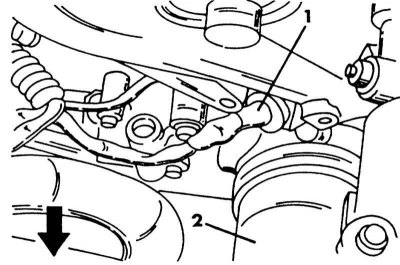
Coolant Temperature Sensor Position (1) next to the oil filter (2).
3. Throttle position sensor (5) responds to the movement of the gas pedal. It converts the throttle position into a signal and sends it to the electronic control unit. The control device determines the idle position of the throttle valve, when the device receives a corresponding signal, and it, for example, stops the fuel supply.
4. Injection valves (3) have small switching valves. When the electronic device sends a signal to the injection valve, the valve coil retracts the needle and fuel is injected into the intake manifold. How long fuel is injected is also determined by the control unit.
5. Fuel pressure control (4) maintains a constant pressure of 3.0 bar in the system. Since the amount of injected fuel depends on the duration of injection, the pressure must be maintained at a given level.
6. The signal coming from the control device is fed to the amplifying stage (11), which controls the primary current circuit of the ignition coil. High voltage is removed from the secondary circuit of the coil. The ignition coil is not a standard type.
7. Air regulator (9) regulates air flow past the throttle when the engine is cold or during warm-up at fast idle. The regulator reacts to the temperature and, depending on it, changes the cross section of the channel. Together (2) located auxiliary air valve, which works with the control valve (7). These interdependent elements receive signals from the control device and regulate the engine idling to a predetermined value. The illustration below shows what the switch module looks like. In the indicated place is the idle adjustment screw.
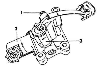
View of auxiliary air valve and related components
1 - X.X adjustment bolt; 2 - additional air valve; 3 - switching valve
7. Speed sensor installed in the speedometer and converts the speed signal into pulses that are fed to the control device. To maintain the idle speed when the engine is subjected to additional load during servo operation, an oil pressure sensor is installed in the high pressure line of the steering system, which provides a load signal to the control unit. It informs the secondary air valve of the required increase in idle speed depending on the size of the load.
8. Located on the block knock sensor engine. If the engine vibrates due to knocking, this is converted by the sensor into a voltage signal, which is fed to the control unit.
9. Fuel filter (6) is in a metal case to withstand the high pressure of the fuel. One hose is connected to the filter from above and below. The filter sits in a spring latch. Before changing the filter (recommended every 40,000 km or every 2 years), lower the fuel pressure in the system to avoid fuel splashing. Install only the appropriate Specifications filter.
10. Adsorber with activated carbon (1) serves the purposes described in Section Exhaust emission control systems for a carbureted engine. All elements related to the ignition system are described in Chapter Engine electrical system.
11. Fuel pump located in the fuel tank. The control device turns on the fuel pump a few seconds after the ignition is turned on, to facilitate starting the engine. When the control device receives a signal from the crankshaft position sensor "180", it knows that the motor is turning and turning on the pump. If this signal is not received, the motor is switched off and the pump is set to a mode that saves battery voltage and ensures safety. The control unit starts the pump via a separate relay.
12. On cars with a catalyst, a lambda probe is installed in the exhaust system. It measures the oxygen content in the exhaust gases and changes the ratio of the amount of fuel and air in accordance with this.
Works on the system
When carrying out any work on the system that cuts off the fuel lines, the fuel pressure must first be reduced. In doing so, proceed as follows:
1. Open the fuse box cover and remove the fuse shown in the illustration. This is the fuel pump fuse. Now start the engine. After a while, it will stall, as it will not receive fuel. Crank the crankshaft two or three more times with the starter to relieve all pressure. Replace the fuse immediately. Now you can disconnect all the fuel hoses between the engine and the body.
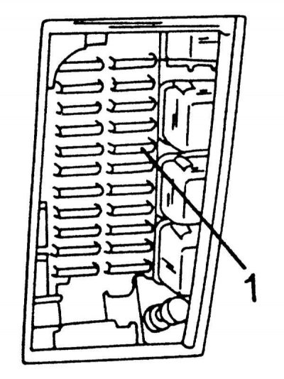
Fuel pump fuse position (1) in the fuse box.
2. For all other, especially electrical work that requires the necessary knowledge, observe the following safety measures:
3. Use only 12V battery.
4. Never disconnect battery cables while the engine is running.
5. Never disconnect the injection valve cables while the engine is running.
6. Never apply devices connected directly to the battery to the injection valves.
7. The air flow meter is very sensitive and should be handled accordingly. It cannot be disassembled. It also should not be flushed with any liquid.
8. The auxiliary air valve cannot be disassembled.
9. Even small leaks in the air intake system can affect engine performance.
10. The electronic control device cannot be repaired.
11. When starting the engine, do not depress the gas pedal. Do not increase engine speed immediately after starting and before shutting down.
12. If there is no fuel in the tank, do not turn on the starter to start the engine, as the fuel pump should not run without fuel.
13. Always connect the cable plugs of the switchgear as described. A bad connection can lead to a power surge and, as a result, damage to the ignition coil and other components. Keep main cabling at least 10mm away from other cables to avoid external impact on cable connections. All cable harnesses must be dry. Always turn the ignition off and disconnect the earth cable from the battery before loosening any connection.