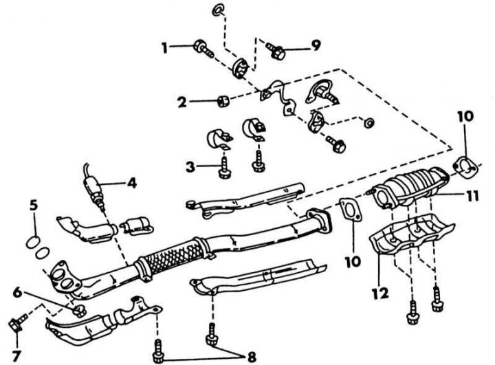
The front of the exhaust system of a car with an SR20DE engine
1 - bolt, 13-16 Nm; 2 - nut, 45-55 Nm; 3 - bolt, 5-6.5 Nm; 4 - lambda probe, 18-24 Nm; 5 - manifold flange gaskets; 6 - nut, 42-49 Nm; 7 - bolt, 21-27 Nm; 8 - bolt, 5-7 Nm; 9 - bolt, 13-16 Nm; 10 - gasket; 11 - catalyst; 12 - heat shields
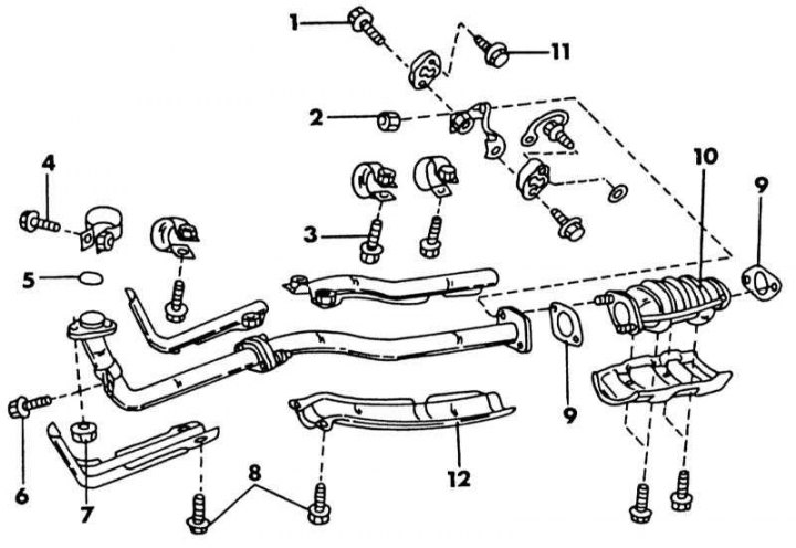
Front of the exhaust system of a carbureted engine
1 - bolt, 13-16 Nm; 2 - nut, 44-56 Nm; 3 - bolt, 5-6.5 Nm; 4 - bolt, 5-6.5 Nm; 5 - exhaust manifold gasket; 6 - bolt, 21-27 Nm; 7 - nut, 29-34 Nm; 8 - bolts, 5-6.5 Nm; 9 - gaskets; 10 - catalyst; 11 - bolt, 13-16 Nm; 12 - heat shields
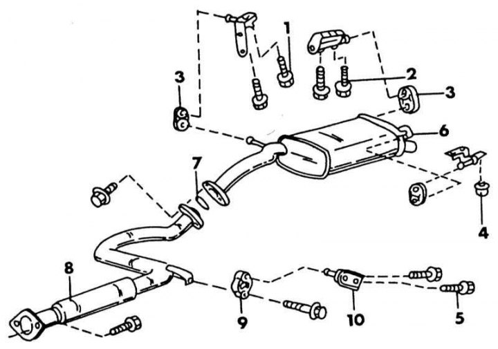
Rear exhaust system
1 - bolt, 6 Nm; 2 - bolt, 13-16 Nm; 3 - rubber suspensions; 4 - nut, 13-16 Nm; 5 - bolts, 13-16 Nm; 6 - main muffler; 7 - gasket; 8 - intermediate pipe; 9 - rubber suspensions; 10 - mounting angle
It is obvious that the exhaust systems of the models considered in this manual have a different design, so we will limit ourselves to describing models with a catalyst. On models without a catalyst, the latter is replaced by a silencer. In the illustrations The front of the exhaust system of a car with an SR20DE engine and Front of the exhaust system of a carbureted engine the front parts of the exhaust system of injection and carburetor engines are shown. On illustrations the back of the system is shown, which, with minor differences, is almost the same for all models. However, the location and attachment of the rear is slightly different, as you will quickly see when viewing the installed system.
Based on these illustrations, do the following:
1. Support the system from below so that the suspension is loosened.
2. Loosen the nuts on the underside of the exhaust manifold and disconnect the muffler downpipe from the manifold. Depending on the version, a single or double downpipe is connected to the manifold.
3. Unscrew all heat shields from the underside of the exhaust system.
4. Remove the nuts and bolt to separate the pipe from the metal bracket.
5. Unscrew the lambda probe from the exhaust pipe side of the muffler, if we are talking about an injection engine.
6. Remove bolts and remove muffler hanger.
7. To remove the front section of the system, remove the nuts, remove the bolts from above and disconnect the pipe from the catalyst.
8. To remove the rear of the system, remove the nuts and loosen the rubber hangers. If only the main muffler and/or pipe need to be removed, remove the fasteners according to illustrations and unscrew the rear pipe on the connecting flange of the muffler or catalytic converter. On the version without catalytic converter, the middle pipe is located between the main muffler and the downpipe and must be loosened accordingly.
9. Disassemble the system as required if the system was removed as a set and insert new parts.
10. When installing the described parts, consider the following points in case the entire system is replaced:
11. All tightening torques are shown in the accompanying illustrations.
- Gaskets between the exhaust pipe of the silencer and the catalyst, the reverse side of the catalyst and the rear pipe, the rear pipe and the main silencer, always replace, even if they still look satisfactory. As a last resort, you can install an old gasket in good condition with a sealant.
- Keep a sufficient distance between the elements of the exhaust system and other parts of the body.
- Screw the lambda probe into the exhaust pipe and tighten with a force of 18-24 Nm. After installation, check all rubber parts. They should not be stretched, otherwise they will burst after a short period of time.
12. Install all hangers according to the wiring diagrams.