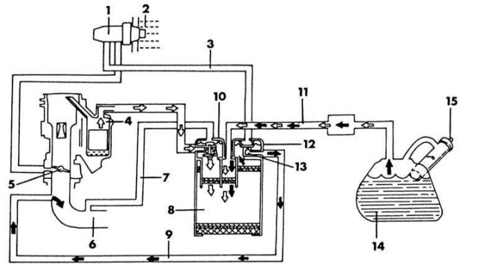
1 - temperature vacuum valve; 2 - engine coolant; 3 - vacuum pipeline; 4 - float chamber; 5 - throttle valve; 6 - intake manifold; 7 - vacuum pipeline; 8 - adsorber with activated carbon; 9 - adsorber purge pipeline; 10 - ventilation switching valve; 11 - pipeline for removing gasoline vapors; 12 - ventilation control valve; 13 - hole for air removal; 14 - fuel tank; 15 - tank cover with vacuum pressure reducing valve
This system serves to reduce the amount of harmful vapors displaced from the supply system that pass through the activated carbon adsorber. The illustration above shows a diagram of the system, which shows how the individual elements are connected to each other.
When the engine is turned off, fuel vapors are drawn from the sealed fuel tank into the canister filled with activated carbon and accumulated there. Gasoline vapors in the carburetor float chamber are also discharged through the external vent line to the canister, since the bleed valve is normally open. When the engine is running, gasoline vapors remain in the charcoal adsorber until they are again drawn to the intake manifold by the air forced through the ventilation duct. As the speed increases, the vacuum also increases and the vent control valve opens, which allows gasoline vapors to return back to the intake manifold. If the engine temperature is less than 70°C, the vent valve closes due to the thermal vacuum valve and thereby interrupts the supply of gasoline vapor to the intake manifold. The ventilation control valve controls the flow of ventilation air in relation to the amount of intake air. If it is necessary to remove parts of the system, first of all remember the order of connecting the individual hoses, especially on the adsorber, so that they can be installed in their original position.