Vehicle check
Note. If the starter fails while starting the engine, perform the following checks.
1. Check the battery status and charge level.
2. Clean the battery terminals, paying particular attention to the cleanliness of the positive terminal and its clamp.
3. Check up a condition and reliability of fastening of contacts of grounding.
4. Turn on headlights and ignition. If the headlights are on, but the starter is not working, this can be regarded as a sign of a short circuit in the starting circuit. Check for engine or starter gear assembly stuck in flywheel ring gear (in these cases, the symptoms will be similar).
5. If the headlights do not burn and the starter does not function, check the ignition switch for an open circuit.
6. Inspect the external wiring for signs of an open circuit. If no defects can be found, the starter should be removed to perform a detailed diagnosis.
Removing
4.2L engine starter assembly
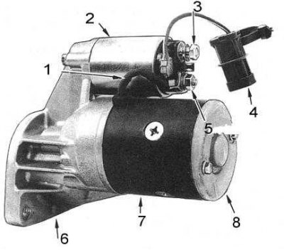
1 - bus pole connector; 2 - electromagnetic traction relay; 3 - main terminal; 4 - connector; 5 - terminal of the pole winding; 6 - rear end cover; 7 - cover on the drive side; 8 - body
1. Disconnect the negative cable from the battery.
2. Disconnect the battery wire from the starter solenoid traction relay.
3. Disunite an electric socket on a starter.
4. Give fixing bolts and remove a starter from the car.
Note. If the starter cannot be removed from the transmission case, try prying it gently with a lever.
Installation
1. Installation is carried out in the reverse order.
2. Lubricate its mating surface with a good quality liquid sealant before installing the starter on the transmission.
Disassembly
Models 3.0 l
3.0L Engine Starter Components
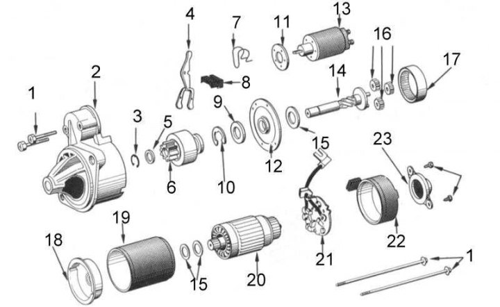
1 - bolts; 2 - cover on the drive side; 3 - retaining ring; 4 - drive lever; 5 - thrust ring; 6 - drive gear; 7 - spring; 8 - anther; 9 - washer; 10 - retaining ring; 11 - plate; 12 - intermediate front cover; 13 - electromagnetic traction relay; 14 - drive gear shaft; 15 - adjusting washer; 16 - planetary gears; 17 - gear wheel with internal gearing; 18 - intermediate back cover; 19 - body; 20 - anchor; 21 - brush holder; 22 - cover from the side of the collector; 23 - screws
1. Disconnect the brush connector bus from the bottom terminal of the traction relay.
2. Give fixing bolts and remove a back boot from a cover from outside a collector.
3. Draw a mark on the relative position of both covers and the starter housing.
4. Turn out through bolts and remove a cover from the case from the collector.
5. Remove the brush holder assembly, housing, armature, and intermediate rear cover from the drive side cover.
6. Remove the intermediate rear cover and shims from the anchor. Note the number of shims.
7. Give the fixing bolts and slightly separate the traction relay from the bracket, disengaging the drive lever from the plunger. Remove the traction relay. Remove the drive arm tension spring and adjusting plate.
8. Remove intermediate front cover, drive gear shaft with planetary assembly, and lever from drive side cover.
9. Use pliers to press down the drive gear thrust washer and remove the retaining ring, thrust washer and drive gear from the gear shaft.
10. Using a small screwdriver, remove the circlip, washer, intermediate front cover, and shim from the drive gear shaft.
11. Thoroughly clean all components, but do not submerge the armature solenoid and drive gear assembly in solvent.
Models 4.2 l
3.0L Engine Starter Components
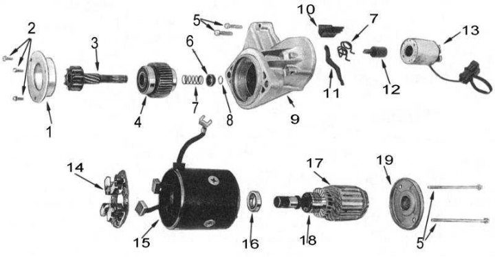
1 - gear casing; 2 - screws; 3 - drive gear; 4 - clutch; 5 - bolts; 6 - bushing; 7 - spring; 8 - retaining ring; 9 - cover on the drive side; 10 - sealant; 11 - drive lever; 12 - plunger; 13 - electromagnetic traction relay; 14 - brush holder; 15 - body; 16 - bearing; 17 - anchor; 18 - collector; 19 - rear end cap
1. Remove the starter from the vehicle.
2. Clamp the starter in the installation position in a vice with soft jaws (behind the cover on the drive side).
3. Loosen the nut of the pole winding terminal and disconnect the wire from the traction relay.
4. Having drawn a risk, mark the relative position of the covers and the body.
5. Give fixing bolts and remove a back face cover from a starter.
6. Remove the housing, armature and brush holder assembly from the drive side cover. Note the position on the O-ring housing.
7. Release the brush springs and remove the brushes from the brush holder.
8. Remove the brush holder and anchor from the body.
9. Having drawn a risk, mark the position of the traction relay in relation to the cover bracket on the drive side.
10. Give the fixing bolts and remove the traction relay, plunger, spring, drive lever, rubber seal and shims from the cover (if they are installed). Try to remember the installation position of the components.
11. Clamp the cover on the drive side in a vise with soft jaws (drive gear up) and give the screws securing the gear housing to the cover.
12. Remove the cover and remove the gear assembly from the cover
13. Clamp the gear in a vise with soft jaws, press the bushing down and remove the circlip from the gear.
14. Remove the bushing with the spring from the gear, then remove the gear from the clutch.
15. If necessary, you can use a pair of screwdrivers to remove the bearings from the clutch. Remember the position of the larger one.
16. If necessary, remove the bearings from the armature using a puller for this purpose.
17. Thoroughly clean all components. Never immerse the hull, armature or clutch in solvent.
Status check
1. Using an ohmmeter, check the brush holder insulator for continuity. Connect one of the probes of the device to the positive side of the brush holder, the second to the negative side. If there is continuity, make the necessary repairs or replace the brush holder.
2. Measure the length of the brushes, compare the measurement result with the requirements tables of sizes and adjustments. Replace brushes if necessary. The brushes should slide freely in the holders - check.
3. Check brush spring forces and compare results with regulations (see tables of sizes and adjustments at the end of the guide). Replace springs if necessary.
4. Check the collector for cavities and burnouts. Wipe it with a rag soaked in gasoline and polish it with fine sandpaper. In case of heavy wear, the manifold can be clamped into the chuck of a lathe and lightly machined with a very sharp cutter at high rotational speeds. After completing the groove, measure the outer diameter of the manifold and compare it with the regulations (see tables of sizes and adjustments at the end of the guide). Cut the insulation between the segments to the required depth.
5. Connect one of the ohmmeter probes to the armature shaft or core and move the other along the generator surface of the collector. If conduction occurs at any of the points, the armature is defective and must be replaced.
6. Check the pole windings for continuity between the winding wire and each of the brushes. If conduction occurs, the pole winding wire is broken.
7. Connect one of the ohmmeter probes to the pole winding wire, and the second to the housing. If there is continuity, replace the pole windings with the housing.
8. Check drive gear teeth for signs of wear and chipping.
9. Make sure the clutch only transmits rotation in one direction. In the opposite direction, the coupling should turn easily and smoothly, and the entire assembly should move freely along the screw splines.
Assembly
Models 3.0 l
1. Lubricate planetary gears, internal gear, and drive arm with high temperature grease.
2. Slide the planetary assembly, shims and intermediate front cover onto the drive gear shaft.
3. Put the washer and circlip on the pinion shaft.
4. Slide the drive gear, thrust ring and circlip onto the shaft.
5. Install the drive arm and drive gear into the drive side cover.
6. Establish a tension spring of the lever and if removed, adjusting plates on the electromagnetic traction relay. Carefully install the traction relay on the cover on the drive side. Track correctness of its arrangement concerning the drive lever. Screw in the mounting bolts of the traction relay and tighten them with the required force.
7. Anchor intermediate rear cover and shims (following the old order).
8. Clip the brushes into their holders and anchor the brush holder assembly, housing and manifold side cover.
9. Install the housing assembly with brush holder and armature on the cover on the drive side (taking into account the landing risk). Screw in the through bolts and tighten them firmly.
10. Install the boot and screw the fixing screws into the cover from the side of the manifold. Tighten the screws firmly.
11. Pull the gear out of the housing by hand so that it rests against the stop and measure the distance from the end of the gear to the surface of the housing.
12. Apply a voltage of 12 V between the bayonet terminal of the traction relay and the terminal of the pole winding on the traction relay. Repeat the measurement of the previous paragraph. Subtract the first result from the second result to determine the axial play of the gear, compare the calculation result with the regulatory requirements (see tables of sizes and adjustments at the end of the guide).
13. If necessary, add an adjusting plate between the bearing surface of the traction relay and the cover on the drive side, or remove the excess.
14. Connect the wire to the terminal of the pole winding of the traction relay and secure it firmly with a nut.
15. Install the starter on the car.
Models 4.2 l
Assembly is carried out in the reverse order of dismantling.
1. If removed, install new bearings in clutch assembly and anchor. Lubricate the armature bearings with high temperature grease. Sealed type clutch bearings are factory packed with grease and do not need to be relubricated.
2. Lubricate the gear teeth, drive gear helical splines, traction relay plunger, and drive lever with high temperature grease.
3. Install the gear in the clutch, install the spring and bushing on the gear.
4. Press the sleeve down and install the circlip on the end of the gear. Make sure the bushing is properly seated on the circlip.
5. Install the gear/clutch assembly into the drive side cover.
6. Install the gear housing on the cover. Install and securely tighten the mounting screws. Check the freedom of rotation of the gear.
7. In the same order, assemble the lever, spring and traction relay.
8. Install the traction relay assembly and rubber seal on the cover on the drive side. Screw in and firmly tighten the bolts of the traction relay.
9. With your hand, pull the gear out of their casing to the stop and measure the amount of its protrusion.
10. Apply a voltage of 12 V between the bayonet terminal of the traction relay and the terminal of the pole winding on the traction relay. Repeat the measurement of the previous paragraph. Subtract the first result from the second result to determine the axial play of the gear, compare the calculation result with the regulatory requirements (see tables of sizes and adjustments at the end of the guide).
11. If necessary, add an adjusting plate between the bearing surface of the traction relay and the cover on the drive side, or remove the excess.
12. Install the anchor in the hull.
13. Install the brush holder assembly into the housing. Insert the brushes into the holders and put the springs on them.
14. Install the o-ring on the body. Make sure it doesn't twist.
15. Install the housing assembly with armature and brush holder on the cover on the drive side. Get alignment of the landing marks.
16. Install the end cap on the body. Screw in the fixing bolts and tighten them firmly.
17. Connect a wire to the pole plug of the traction relay and fasten it firmly with a nut.
18. Install the starter on the car.