Lubricate the piston pin and connecting rod eye well.
Insert the piston pin circlip from one side into the piston. Check that it sits well in the groove.
Press the pin with a suitable mandrel into the heated connecting rod.
The following instructions must be observed during assembly:
- 1. Arrow on piston crown (or drawn, or embossed on new pistons - see illustration) should point towards the front of the engine.
- 2. Cylinder number designations on connecting rods and bearing caps must match (illustration). Consider the difference between injection and carbureted engines.
1. Check up that pistons after assembly freely could move on rods.
2. Piston rings are installed either with special pliers from the side of the piston crown (illustration), or using the metal strips mentioned in the removal. When the ring is flush with the groove, the metal strip is removed so that the ring sits in the groove. It is possible to mix up two compression rings, so pay attention to their cross section before installing them. If the rings are well marked, it is rather difficult to confuse them. In addition, both compression rings are marked on the same side (letter "R" can be knocked out on a carbureted engine) which should be visible from the side of the piston crown.
3. Lay the assembled pistons on a clean surface prior to installation and cover them to keep them free of dust. Since the parts are already lubricated, care must be taken to ensure that foreign bodies do not get on the pistons.
Assembly of pistons and connecting rods
1. Lubricate the cylinder mirror well.
2. Insert connecting rod bolts and connecting rods, insert bearing shells.
3. Position the connecting rods according to the cylinder numbers. The oil spray holes must be on the specified side of the cylinder block. On illustrations shows how pistons and connecting rods should be located on an injection engine. The illustration below shows the position of the parts on a carburetor engine.
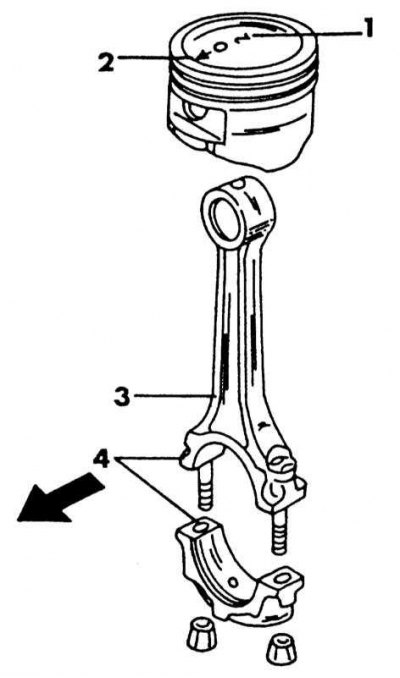
Correct assembly of the piston and connecting rod on a carbureted engine. The arrow points to the front of the engine
1 - piston size; 2 - mark "before"; 3 - oil spray hole; 4 - cylinder number
4. Marks on the bottom of the pistons, i.e. mark on the edge (injection engine) or arrow (carbureted engine) should point towards the front of the engine.
5. Position the piston ring locks 120°apart from each other. The illustration shows how the ring locks are offset from the piston pins. On engines of both versions, the rings are located in the same way.
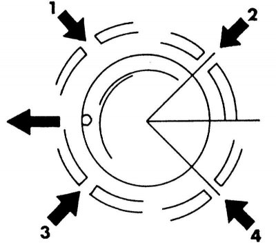
The location of the locks of the piston rings. Large arrow points to the front of the engine
1 - lock of the expansion element of the oil scraper ring; 2 - lock of the upper ring and the upper element of the oil scraper ring; 3 - lock of the second ring; 4 - lock of the lower element of the oil scraper ring
6. Apply a clamping band for the piston rings and press the rings into the grooves. Check that they are correctly in place. If no tie band is available, you can use a large hose clamp or place thin metal strips around the rings and squeeze the ends so that the rings fit into the grooves. Insert the piston after it has been checked again that there are no foreign objects on it. If a hose clamp is used, it can be installed around the ring until the ring is seated in the cylinder. Then move the clamp to the next ring and insert it into the hole. Then do the same with the top ring.
7. Place a short piece of rubber or plastic hose over the connecting rod bolts to avoid scratching the hole.
8. Turn the crankshaft until the two crankshaft journals are in the BDC position.
9. Insert the connecting rod from above into the hole. To do this, lay the engine on its side so that the connecting rod can be installed on the neck and not scratch the hole or the crankpin. The connecting rod bearing shells should already be in the connecting rod, with the lugs in the recesses and both oil holes in line.
10. Push the piston until the rings fit into the hole as shown in the illustration below, and the end of the connecting rod will fit on the crankshaft journal.
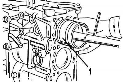
Piston installation. Mounted strap (1) slides when the piston is pushed in
11. Insert the second bearing shell, lubricate the shell well and press the cover against the connecting rod bolt and hammer lightly. Sections of the rubber hose must be removed beforehand. Be sure to make sure that the numbers on the connecting rod and the bearing cap are on the same side and match each other, as at the last moment you can make a mistake.
12. Lubricate the nut seating surfaces on the connecting rod bearing caps.
13. Tighten the new connecting rod nuts alternately with a force of 14-16 Nm. To withstand the tightening torque, the cylinder head must be installed on the sealing surface. Have an assistant hold the block and tighten both connecting rod bearings on top. In the same way, re-tighten the nuts of the connecting rod bearings with a force of 40-45 Nm for an injection engine or 23-29 Nm for a carburetor engine.
14. After installing the connecting rod, turn the crankshaft several times to immediately identify jamming.
15. Recheck the designations of all connecting rods and check that the pistons are facing the correct direction.
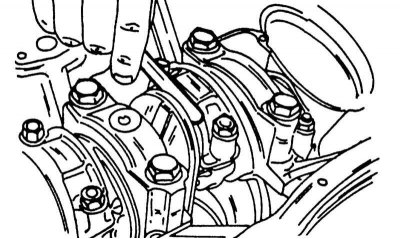
Measurement of axial play of connecting rods mounted on the crankshaft. The feeler gauge is inserted between the connecting rod and the working surface of the crankshaft.
16. Using a feeler gauge, measure the clearance between the side surface of the connecting rod and the crankshaft as shown in the illustration. This is the axial play of the connecting rod bearings, which should be no more than 0.50 mm. If exceeded, replace the corresponding connecting rod or crankshaft.