


2. If a ridge has formed at the top of the cylinders, it must be removed with a reamer or scraper without damaging the cylinder wall. The formation of a ridge indicates increased wear of the cylinder.
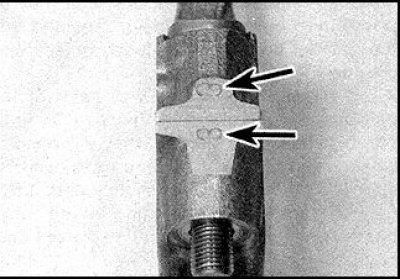
3. The cylinder number must be stamped on the connecting rod and on the connecting rod cap (indicated by arrows), to which this connecting rod belongs. Cylinder N1 is located on the front cover side. If the numbers are not visible, apply them with paint or punch them. Apply marks on the ground side surface of the connecting rod and cover.
4. Set pistons of cylinders 1 and 4 to the BDC position.
5. Unscrew the connecting rod cap nuts of the connecting rod of the 1st cylinder. Remove the cap and take out the lower connecting rod bearing. If the bearing is to be installed again, then glue it with adhesive tape to the removed cap.
The source is published on the portal www.NissanBook.ru
6. Tape the threads of the connecting rod cap bolts.
7. Using the handle of a hammer, push the piston into the cylinder and pull the piston out through the top of the cylinder block. Remove the upper connecting rod bearing and tape it to the removed connecting rod.
8. Place the cover on the connecting rod and secure it with nuts, without disturbing the previous order of assembly of the parts.
9. Repeating the above operations, remove the connecting rod with the piston of the 4th cylinder.
10. Similarly, remove the connecting rods with pistons from the 2nd and 3rd cylinders.