


2. Remove the tray (Chapter 7).
3. Loosen the bolt and remove the oil suction pipe and mesh filter.
4. Note that the lower connecting rod cap and connecting rod are numbered (photo). Number 1 is on the toothed belt side of the drive.
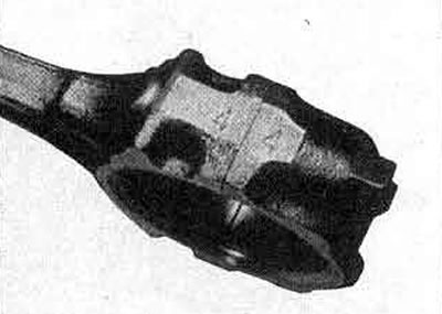
9.4 Connecting rod and cap numbers correspond to cylinder numbers
5. Check the engine cylinder wear. If a step is felt, it must be removed to allow the piston rings to come out freely when removed.
6. Unscrew the union nuts of the lower connecting rod head, remove the cover with the liner.
7. Push the piston with the connecting rod up out of the cylinder block.
8. If the liners are to be used again, mark their position on the lids.
9. Repeat the steps on the remaining three assemblies.
10. If the pistons were removed to install new piston rings to reduce oil consumption, then use rings of the same size.
11. To remove the piston rings, insert three thin plates evenly in a circle inside the top ring.
12. Remove the ring by pulling it upwards from the piston.
13. Remove the remaining rings in the same way.
14. Clean the piston ring grooves from carbon deposits. You can use a piece of an old ring for this.
15. Check that the return oil holes in the ring grooves are clean.
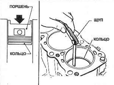
Figure 1.15 Checking the piston ring cut clearance
16. Check the ring gap using a feeler gauge blade (Figure 1.15). If the gap is less than specified, increase it by filing down the end of the ring.
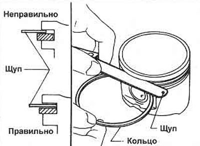
Figure 1.16 Checking the piston ring side clearance
17. Check the side clearance of each ring in the groove using a feeler gauge blade (Figure 1.16).
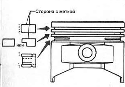
Figure 1.17 Piston ring identification
18. Install the rings in the reverse order of removal. Position the ring cuts as shown in Figure 1.18.
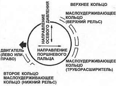
Figure 1.18 Location of piston ring cut gaps
19. If new rings are used, sand their top edges. Also sand down the step at the top of the cylinder bore.
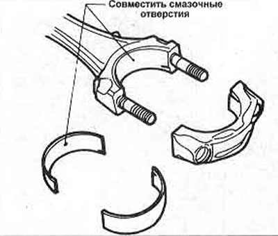
Figure 1.19 Aligning the bearing shell with the connecting rod
20. If new connecting rod bearings are used, use the same size as the originals.
21. Install the bearing shells into the caps and connecting rods, the upper bearing shell has a lubrication hole that must exactly match the hole in the connecting rod (Figure 1.19). 22 Generously lubricate the piston rings and compress the piston with a mandrel.
23. Lower the connecting rod of piston #1 into the engine cylinder so that the drift sits squarely on the surface of the block. Make sure that the mark on the piston head faces the end of the engine with the toothed belt drive (photo).
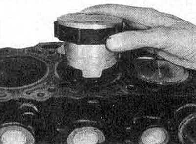
9.23A Insert the piston/connecting rod into the cylinder bore,...
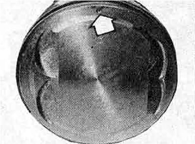
9.23B... so that the mark on the piston head faces the timing belt
24. Tapping the wooden handle of the hammer into the center of the piston head, sink the piston with rings into the cylinder. Remove the mandrel (photo).
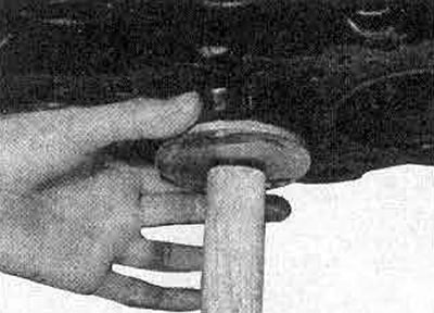
9.24 Inserting the piston into the cylinder bore
25. Place the bottom of the connecting rod on the crankshaft and seat the connecting rod cap (with insert) so that the corresponding numbers are combined.
26. Tighten the nuts (lightly lubricating the threads) and tighten them to the tightening torque specified in Specifications (photo).
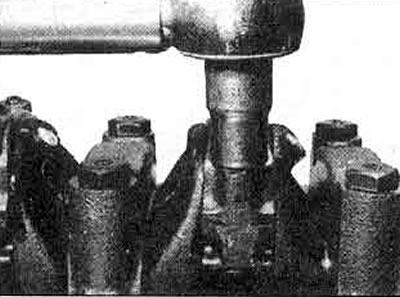
9.26 Tightening the connecting rod union nut
27. Repeat the described steps with the remaining pistons.
28. Install the oil pickup tube and strainer, oil pan and cylinder head as described earlier in this Section.
29. Fill the engine with oil.