


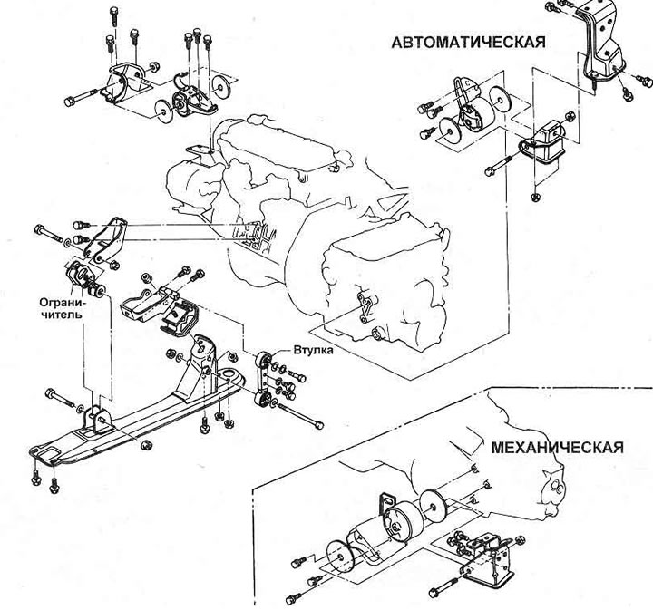
Figure 1.20 Engine/transmission mount
1. The mounts can be replaced by hanging the engine with the transmission on a winch or supporting it with a jack (photo).
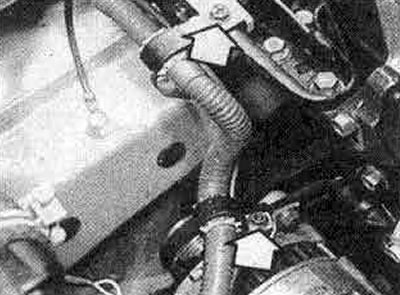
10.1A Unscrew the wiring clamps (marked with arrows) and disconnect the generator wiring...
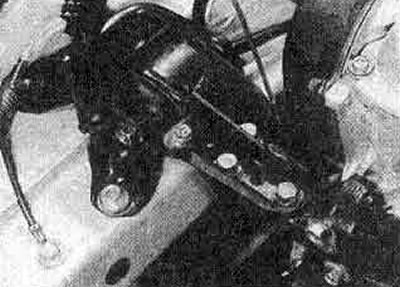
10.1B... before removing the right engine mount
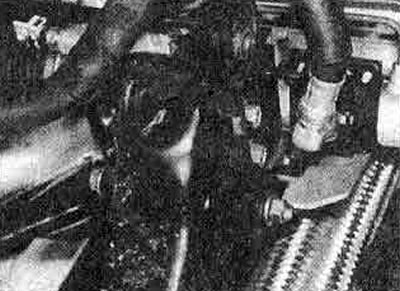
10.1C Rear Engine/Transmission Sub-Mount (engine removed)
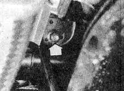
10.1D Rear Engine/Transmission Mount Nut Visible Below (see photo 12.31)
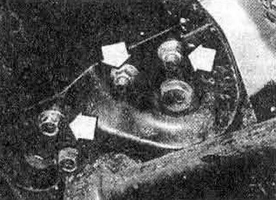
10.1E Rear engine bracket longitudinal member fasteners (marked with an arrow)
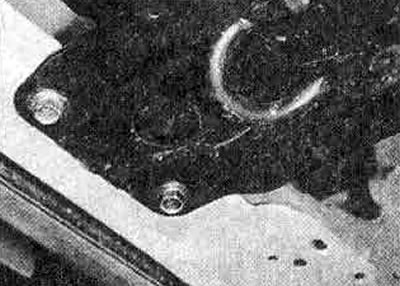
10.1 F Front engine bracket longitudinal member fastenings
2. The component including the flexible insulator must be replaced if the rubber becomes sticky or deformed.
3. Tighten the fasteners in the following order:
- (a) Right mount
- (b) Left mount
- (c) Rear (main) mount
- (d) Remove the jack or winch so that the entire weight of the engine/transmission rests on the mounts, then tighten the bolts and nuts on the lower rear mount and front buffer rod in the order shown in Figure 1.21.
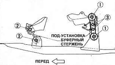
Figure 1.21 Front and rear engine/transmission mount compression sequence
Adjustment
4. If the engine vibrates heavily at idle speed, check that all fasteners are in good condition and securely tightened to the tightening torques specified in Specifications, then check the following.
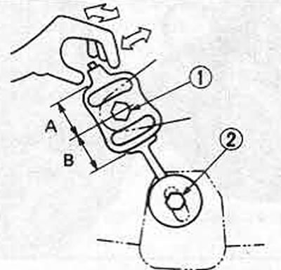
Figure 1.22 Adjusting the front buffer rod engine/transmission
5. Using Figure 1.22, check that the distances A and B of the front buffer rod (photo) are equal, and the distances between bolts 1 and 2 should be 100 mm. Loosen the mounting bolts and nuts, adjust if necessary.
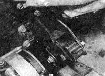
10.5 Front Mount Buffer Rod Engine/Transmission (the engine is installed)
6. Clamp the top end of the buffer rod and move it back and forth and side to side; it should move smoothly. If not, loosen bolts 1 and 2 and retighten them in reverse order. If the rod still does not move smoothly, replace it (photo).
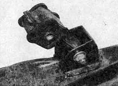
10.6 Replace the buffer rod if it moves harshly
See the original on the resource (nissanbook.ru)
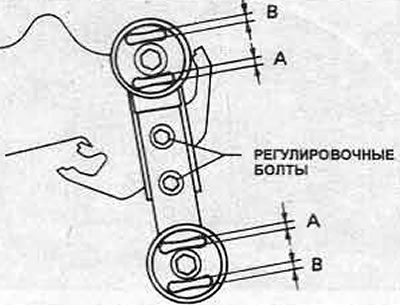
Figure 1.23 Adjusting the rear engine/transmission sub-mount (Chapter 10)
7. Using Figure 1.23, check that the rear lower mount clearances A and B are equal when the engine is idling; on automatic transmission models, check gap A with the transmission in D and gap B with the transmission in R. If either pair of gaps is closed, loosen the two adjusting bolts and change the length of the lower setting until the correct adjustment is obtained (photo).
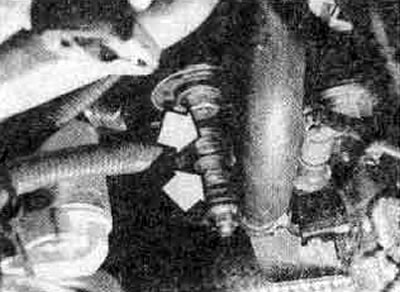
10.7 Rear Engine/Transmission Sub-Mount (the engine is installed) - adjusting bolts are marked with arrows
8. If the front and rear mounts are adjusted correctly, check that the radiator does not vibrate when the engine is idling. If there is vibration, check the radiator mounts and replace them if necessary (Section 2).
9. On models with automatic transmission, check the vibration of the dynamic shock absorbers at idle speed (position D selected). If any shock absorber does not vibrate, replace it.
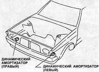
Figure 1.24 Dynamic Damper Locations - Automatic Transmission