Selection of liners for new main bearings
Attention! Description applies to standard size main bearings only. Repair inserts are not divided into size groups. New main bearings are selected according to the identification codes printed on the crankshaft and on the cylinder block.
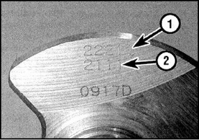
On the crankshaft, the codes are printed on the cheek of the neck of the 1st cylinder (from the side of the chain cover). The code of five digits refers to the diameters of the main bearings - the first digit indicates the code for the 1st crankshaft main journal, and the fifth indicates the code for the 5th journal.
Attention! In some engines, four-digit codes are also applied to the cheek of the crankshaft, which indicate the size group of the connecting rod bearings (see subsection 3.2.2.10.2).
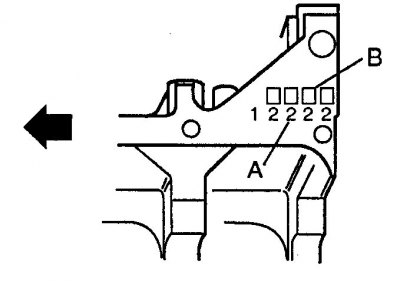
On the cylinder block, the dimension codes are stamped into the base on the flywheel side.
To select the main bearing shells, you need to find out the size group for boring under the liner stamped on the cylinder block and the size group code of the corresponding main journal, which is printed on the crankshaft, and then, using the attached table, determine the desired liner, guided by the color marking, which is in the form of a dot applied to its lateral surface.
| crankshaft code | Code on the cylinder block | Main bearing marking |
| 0 | 0 | black |
| 0 | 1 | brown |
| 0 | 2 | green |
| 1 | 0 | brown |
| 1 | 1 | green |
| 1 | 2 | yellow |
| 2 | 0 | green |
| 2 | 1 | yellow |
| 2 | 2 | blue |
Checking clearances in main bearings
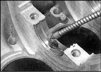
1. Clean the outer surface of the new main bearings, the surfaces of the bearing bores in the cylinder block and in the main bearing caps.
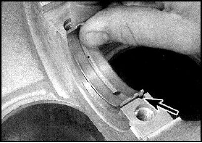
2. Install the top bearings by aligning the tabs with the recesses in the cylinder block (arrow).
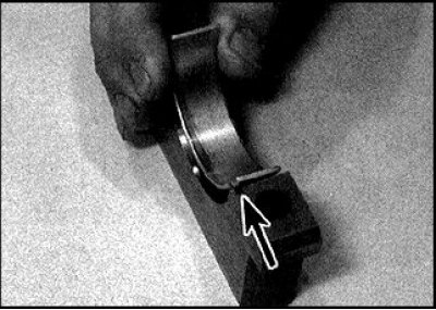
3. Install the bottom bushings into the covers, also aligning the tab with the recess (indicated by an arrow).
4. Do not touch the working surface of the earbuds with your fingers. Note that all upper main bearings have an oil groove and oil inlet. The bottom liners are solid. If the gap will be checked on the old liners, then make sure that they are installed in their original places.
5. The gap can be checked in two ways.
6. When determining the gap in the first way, install the covers (or lid frame) main bearings together with liners on the cylinder block, tighten the bolts to the specified torque and measure the inner diameter of each assembled pair of liners. The main bearing clearance is defined as the difference between this diameter and the diameter of the crankshaft main journals.
7. Second way (more accurate) consists in the use of a plastic gauge wire.
8. With the main bearings in place, carefully position the crankshaft. The root necks must be dry and clean.
9. Prepare several pieces of Plastigage plastic gauge wire, slightly shorter than the width of the main bearings, and place one piece on each crankshaft main journal, parallel to the crankshaft axis.
10. Install the covers with the bottom bushings without disturbing their orientation.

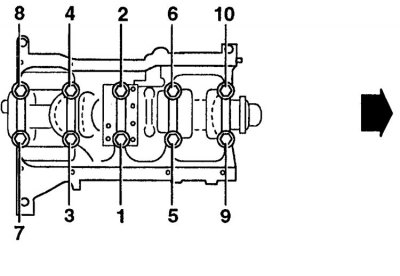
11. Tighten the bolts to the specified torque, in the sequence shown. Tighten the bolts with the same, constantly increasing torque. During tightening, the position of the wire segment should not change, the rotation of the crankshaft is not allowed.
12. Loosen the cap screws in reverse order, backing out one turn at a time.
13. Remove covers (or frame), without disturbing the position of the flattened wires and preventing the crankshaft from turning.
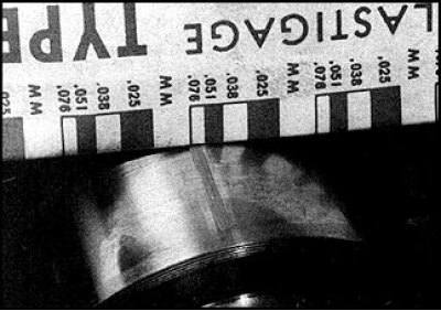
14. Compare the width of the crushed wires with the scale on the package and determine the clearance in the main bearing. Compare with standard value.
15. If the gap differs from the standard, then the reason may be the wrong selection of liners (or their increased wear if used liners were checked).
16. Before concluding that the bearings need to be replaced, make sure that there is no dirt or oil between the covers or the cylinder block and the bearing when measuring.
17. If the width of the flattened wire from one edge is greater, then this indicates a tapered neck.
18. If the clearance differs from the norm when measuring with old liners, then repeat the measurements with new liners.
19. If, with new liners, the gap exceeds the norm, then you should seek advice from a car service. It may be necessary to regrind the crankshaft journals and replace the liners with repair ones.
20. If necessary, purchase liners of the appropriate size group and repeat the procedure for measuring the clearance in the main bearings.
21. When finished, scrape off the remaining gauge wire from the crankshaft main journals without damaging the surface.
Final crankshaft installation
1. Carefully remove the crankshaft from the cylinder block.
2. Install the main bearing shells in place.
3. If new liners are installed, thoroughly wash them in kerosene.
4. Wipe dry the liners and connecting rods.
5. Liberally lubricate the surfaces of the liners installed in the cylinder block with fresh engine oil.
6. Lightly grease the thrust washers and attach them to both sides of the 3rd main bearing.
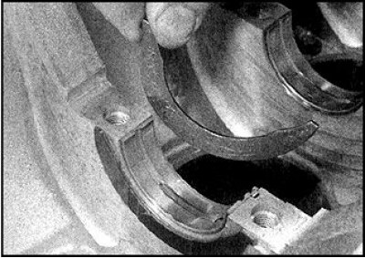
7. Pay attention to the oil grooves on both half rings facing away from the cylinder block.
8. Install the crankshaft in the cylinder block and check the end play.
9. Thoroughly clean the split planes of the main bearing caps and cylinder block from grease.
10. Lubricate the bottom bearing surfaces with fresh engine oil. Make sure that the mounting tabs on the bushings fit into the recesses in the covers.
11. Install the covers in their original places, guided by the marks made.
12. Tighten the bolts by hand.
13. Tighten the cap bolts in sequence to approximately half of the specified torque. Then, repeating the procedure, tighten the bolts to the specified torque.
14. Check the freedom of rotation of the crankshaft.
15. Install piston rods.
16. Apply a mark indicating the depth of the gland in the holder and remove the gland by prying it with a screwdriver.
17. Press in a new oil seal with light blows of a hammer, to a depth that corresponds to the applied mark.
18. Apply a bead of sealant to the split surface of the oil seal holder and install to the cylinder block.
19. Tighten the bolts to the specified torque.
20. Install the flywheel, camshaft timing chains and oil pan.