


Note: The following procedures require a micrometer and a plunger-type dial gauge.
Removal
1. Remove the engine from the vehicle, then remove the cylinder head, oil pan, oil pump pickup, timing belt cover, timing and drive chains, and flywheel/drive plate.
2. Loosen the mounting bolts and, carefully prying, remove the crankshaft rear oil seal holder from the cylinder block and shaft journal.
3. Make sure that the connecting rods and their lower head caps have identification marks (if necessary, apply them yourself).
4. Loosen the mounting nuts and remove the connecting rod lower head caps, stacking them in the order they are placed on the engine. Lift the connecting rods slightly, removing their lower heads from the shaft journals, but without pushing the pistons out of the cylinders.
5. Insert the blades of the feeler gauge between the crank web and the sixth main bearing to check the axial play of the crankshaft. Push the shaft until it stops against the front edge of the central main bearing, then move the shaft forward until it stops to determine the axial play.
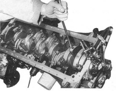
Note: Alternatively, shaft end play can be determined using a plunger-type digital gauge mounted opposite the end of the shaft journal (see accompanying illustration).
6. If the axial play exceeds the permissible value (see size and adjustment tables at the end of the Manual), replace the center main bearing assembly.
7. Using the Plastigage measuring kit, check the crankshaft main bearing clearances:
- Remove the first bearing cap and thoroughly wipe the shaft journal and bearing shell with a clean, lint-free cloth.
- Place a piece of calibrated plastic wire from the measuring kit (equal in length to the width of the bearing) along the shaft neck.
- Install the bearing cover and tighten its mounting bolts to the required torque.
Note: Do not rotate the shaft with the measuring wire placed on its journal.
- Loosen the bolts and carefully remove the cover with the lower bearing shell.
- Using the scale on the Plastigage kit packaging, measure the width of the flattened calibrated wire to determine the bearing clearance.
- The widest section of the flattened wire corresponds to the smallest gap, and vice versa.
- Check the clearances in the remaining bearings in the same manner.
8. Carefully remove the crankshaft from the engine crankcase, making sure that the upper main bearing shells do not fall out or become damaged (if they are to be reused).
9. If the liners are to be replaced, remove the old ones from their beds in the unit.
10. Install the new rear crankshaft oil seal into the holder.
Checking the status
1. Check the crankshaft main and connecting rod journals for signs of wear, taper and out-of-roundness. If the degree of wear exceeds the permissible values (see size and adjustment tables at the end of the Manual) the relevant (main or connecting rod) the necks should be turned to the nearest standard repair size, selecting the appropriate size (with disparagement) bearings. Remember that even if only one of the journals is worn or defective, all journals in the set must be machined (main or connecting rod respectively).
2. If the degree of wear is such that turning the journals will not help to correct the situation, the crankshaft must be replaced.
3. Check the thrust surfaces of the central main bearing for cavities and wear marks. If necessary, replace the thrust bearing shells, which should bring the crankshaft axial clearance into compliance with the regulatory requirements (see size and adjustment tables at the end of the Guide).
4. Even if the clearances in the main bearings are considered satisfactory, check their liners for scratches, scoring, peeling, cavities and traces of wear. If necessary, replace the defective liners in pairs with new ones of the appropriate size.
Installation
Installation is carried out in reverse order.
1. Check the reliability of the patency of all oil flows and do not forget to thoroughly wipe all journals (main and connecting rod) with a clean, lint-free cloth.
2. Thoroughly wipe all new or old bearings, then lubricate them with clean engine oil. Make sure the bearings are installed correctly in the corresponding beds of the block, caps or connecting rod heads.
3. Place the crankshaft into the cylinder block, guiding the connecting rod journals into the heads of the corresponding connecting rods.
4. Place the bearing caps on the corresponding connecting rods and block bearings, tighten the mounting bolts/nuts to the required torque (see size and adjustment tables at the end of the Guide).
5. If the bearing shells have been replaced, check the clearances in them using the Plastigage measuring kit.
6. Install the rear oil seal retainer, timing and drive chains, flywheel/drive plate and any other removed components.
(See the original on the resource: «NISSANBOOK.ru»)