Removal and disassembly
1. Remove the timing chain cover and oil pump drive sprocket with chain.
2. Loosen the clamps and disconnect the fuel plugs from the open ends of the hoses to prevent dirt from entering the fuel system.
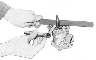
3. Give fixing bolts and remove the fuel pump from the engine.
4. Give fixing bolts and nuts and remove the oil pump from a forward part of the engine. Discard the O-ring.
5. Give bolts of fastening of forward and back covers of the oil pump, remove covers from the pump case (oil pump components are shown in the accompanying illustration).
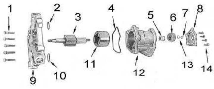
1 - bolts; 2 - sealing ring; 3 - internal gear (rotor); 4 - sealing ring; 5 - bearing; 6 - cam; 7 - nut; 8 - back cover; 9 - front cover; 10 - sealing ring; 11 - outer gear (rotor); 12 - body; 13 - washer; 14 - bolts
6. Loosen the fuel pump drive cam nut, then remove the washer and cam from the oil pump shaft. Remove the inner gear assembly from the oil pump housing (rotor) with shaft and external gear (rotor).
7. Remove the spring from the front cover of the pump (s) pressure reducing valve and valve plunger (see accompanying illustration).
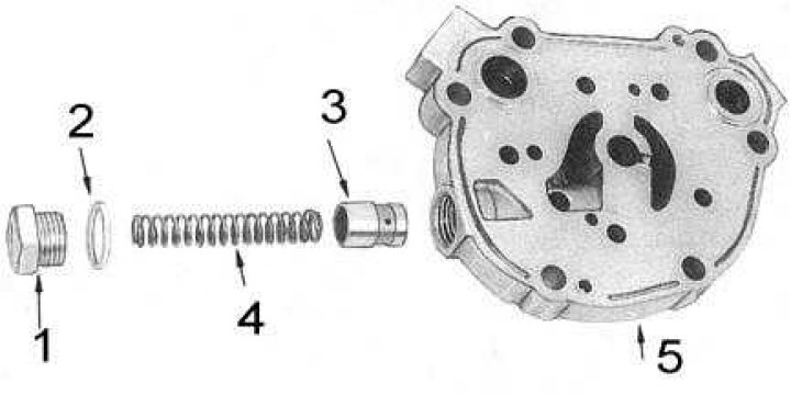
1 - cork; 2 - washer; 3 - plunger; 4 - spring; 5 - front cover
Status check
1. Thoroughly wash the oil pump components in solvent and dry them naturally.
2. Check pump inner and outer gears for signs of wear. Replace defective components.
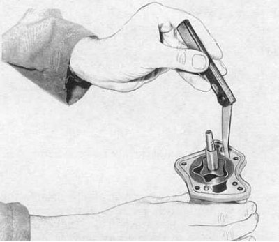
3. Temporarily install both gears back into the pump housing and use a blade-type feeler gauge to check the clearance between the outer gear and the pump housing (see accompanying illustration). Compare measurement result with regulatory requirements (see tables of sizes and adjustments at the end of the guide). Replace pump if necessary.
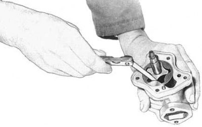
4. Measure the clearance between the teeth of the inner gear and the shoulders of the outer (see accompanying illustration). If the limit is exceeded, replace the pump.
5. Press the edge of the flatness meter against the end of the pump housing and measure the backlash of the gears (see accompanying illustration). Replace pump if necessary.
6. Check the relief valve plunger for nicks and scratches. The plunger must have a sufficiently tight fit in the pump head. Check the spring for loss of applied force and broken coils.
7. Inspect the fuel pump drive cam for cavities and burrs, replace if necessary.
8. Use a hammer and drift to remove the inner gear shaft needle roller bearing from the pump housing. Discard the bearing. Check the condition of the bearing seating surface on the pinion shaft. In case of scoring and roughness, replace the shaft.
Assembly and installation
1. Using a punch and drift, install a new needle bearing into the pump housing.
2. Lubricate all components liberally with engine oil and install the gears in the pump housing.
3. Install the front cover with a new sealing ring, tighten the fixing bolts in several stages with a force of 7÷8 Nm.
4. Prime pressure reducing valve plunger with spring (ami) into the front cover of the pump, tighten the plug with a force of 39÷69 Nm, remembering to change its sealing washer.
5. Install the fuel pump drive cam and tighten the fixing nut with a force of 16÷19 Nm.
6. Lay a continuous pad of sealant with a cross section of 2÷3 mm into the groove in the back cover of the pump, then press the cover against the pump body for no more than ten minutes and fix it with bolts. The tightening torque of the bolts must be 7÷8 Nm.
7. Place a pad of sealant with a ø section of 2÷3 mm into the groove of the front cover of the pump, install new O-rings on the cover, then press the assembly against the pump housing. Tighten the fixing bolts with a force of 7÷8 Nm.
Note. Allow the sealant to dry for at least thirty minutes before starting the engine.
9. Install the fuel pump with a new insulating assembly. Tighten the fixing bolts firmly.
10. Install the drive sprocket/chain assembly, timing chain cover, and crankshaft pulley.