Selection of liners for new main bearings
Attention! Description applies to standard size main bearings only. Repair inserts are not divided into size groups.
Size group codes for main and connecting rod bearings
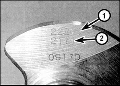
1. Main bearings
2. Connecting rod bearings
New main bearings are selected according to the identification codes printed on the crankshaft and on the cylinder block.
On the crankshaft, the codes are printed on the cheek of the neck of the 1st cylinder (from the side of the chain cover). The five digit code refers to the diameters of the main bearings, the first digit is the code for the 1st crankshaft main journal, and the fifth is the code for the 5th journal.
Attention! In some engines, four-digit codes are also applied to the cheek of the crankshaft, which indicate the size group of the connecting rod bearings (see subsection 3.2.2.10.2).
Codes of size groups of bores for main liners
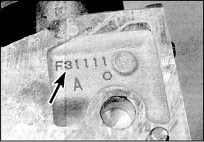
On engines, the codes for the size groups of bores for the main bearings are stamped at the base of the cylinder block (indicated by an arrow).
On the cylinder block, the dimension codes are stamped into the base on the flywheel side. On engines there is only a code of five digits, the first digit in this code refers to the 1st crankshaft main journal, and the fifth to the 5th neck.
To select the main bearing shells, you need to find out the size group for boring under the liner stamped on the cylinder block and the size group code of the corresponding main journal, which is printed on the crankshaft, and then, using the attached table, determine the desired liner, guided by the color marking, which is in the form of a dot applied to its lateral surface.
| crankshaft code | Code on the cylinder block | Main bearing marking |
| 0 | 0 | black |
| 0 | 1 | brown |
| 0 | 2 | green |
| 0 | 3 | yellow |
| 1 | 0 | brown |
| 1 | 1 | green |
| 1 | 2 | yellow |
| 1 | 3 | blue |
| 2 | 0 | green |
| 2 | 1 | yellow |
| 2 | 2 | blue |
| 2 | 3 | pink |
| 3 | 0 | yellow |
| 3 | 1 | blue |
| 3 | 2 | pink |
| 3 | 3 | white (or missing) |
Checking clearances in main bearings
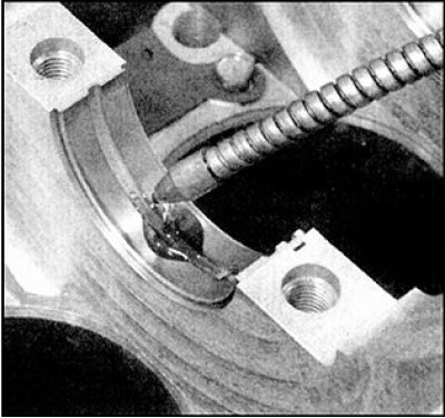
1. Clean the outer surface of the new main bearings, the surfaces of the bearing bores in the cylinder block and in the main bearing caps.
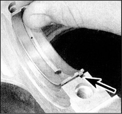
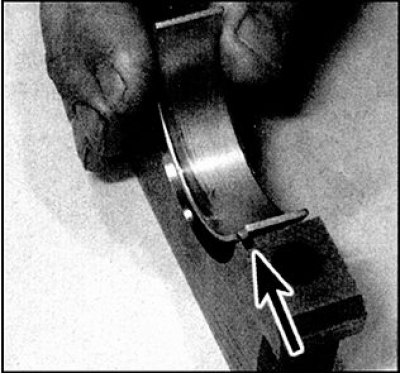
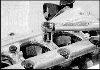
2. Press down on the insert and place it in place. Make sure the protrusion (indicated by an arrow) on the bearing shell went into the selection in the bore of the cylinder block or in the frame of the main bearing caps. Do not touch the working surface of the earbuds with your fingers.
3. Note that all upper main bearing shells have an oil groove and oil inlet. The bottom liners are solid.
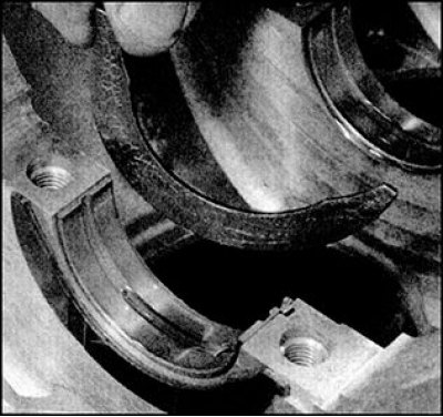
4. Install the bottom liners in the covers (there is no groove and hole on these liners), also aligning the protrusion with the recess.
5. If the gap will be checked on liners that were in operation, then make sure that the liners are installed in their original places. The gap can be checked in two ways.
6. When determining the gap in the first way, you need to install covers (or lid frame) main bearings together with liners on the cylinder block (for measurements in this way, you will need special measuring instruments - a bore gauge with a dial indicator, or a telescopic micrometer, and an ordinary micrometer). Tighten the cover bolts (frame) with the specified torque and measure the inner diameter of each assembled pair of bearings. Main bearing clearance is defined as the difference between the inside diameter of the assembled main bearings and the measured diameter of the crankshaft main journals.
7. Second way (more accurate) consists in the use of Plastigage plastic calibration wire of round cross section (invented and produced in the USA). The wire is flattened between the bearing and the crankshaft journal. After removing the bearing cover, the wire remains flattened. By comparing the width of the crushed wire with the scale supplied with the kit, you can determine the clearance in the bearing. Calibration wire can be purchased from the dealer's car service. If the wire is not available from the dealer, it can be obtained by inquiring with an agent specializing in the supply of engine parts and obtaining information about the availability of this product in your area. Checking the clearance with a gauge is performed as follows.
8. With the main bearings in place, carefully position the crankshaft. No lubrication on the crankshaft journals is allowed. The root necks must be dry and clean.
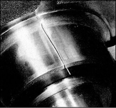
9. Prepare several pieces of Plastigage plastic gauge wire, slightly shorter than the width of the main bearings, and place one piece on each crankshaft main journal, parallel to the crankshaft axis.
10. Install the covers with the bottom bushings in place. When installing the covers, be guided by the marks on them to install the covers in their original position.
11. Install the cast frame of the main bearing caps, install the bolts and tighten them. During tightening, the position of the wire segment should not change, the rotation of the crankshaft is not allowed.
12. On all engines, remove the cap screws. Loosen the bolts in reverse order one turn at a time. Turn out and get bolts from get them from the block of cylinders.
13. Remove main bearing caps (or lid frame), again making sure that the position of the flattened calibration wires does not change and the crankshaft does not turn.
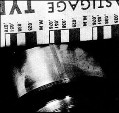
14. Compare the width of the crushed wires with the scale on the package and determine the clearance in the main bearing. Compare with standard clearance.
15. Gap measurement by comparing the width of the crushed gauge wire with the scale on the packaging
16. If the gap differs from the standard, then the reason may be the wrong selection of liners (or their increased wear if used liners were checked). Before concluding that the bearings need to be replaced, make sure that there is no dirt or oil between the covers or the cylinder block and the bearing when measuring. If the width of the flattened wire from one edge is greater, then this indicates a tapered neck.
17. If the clearance differs from the norm when measuring with old liners, then repeat the measurements with new liners. If, even with new liners, the gap exceeds the norm, then you should seek advice from the dealer's car service, or a specialist in this engine, in order to get advice on how to proceed. It is also possible that you will have to regrind the crankshaft journals and replace the liners with repair ones.
18. If necessary, purchase liners of the appropriate size group and repeat the procedure for measuring the clearance in the main bearings.
19. When finished, scrape off the remnants of the calibration wire from the main journals of the crankshaft with a fingernail or a wooden chip, without damaging the surface.
Final crankshaft installation
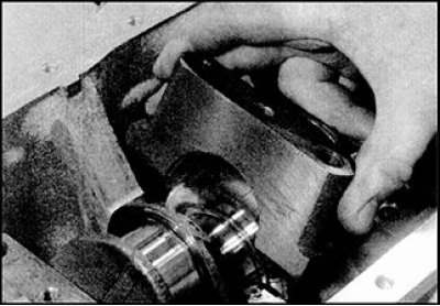
1. Carefully remove the crankshaft from the cylinder block.
2. Install the main bearing shells in place, guided by paragraphs. 5 and 6. If new liners are installed, thoroughly wash them in kerosene to remove any remaining preservative. With a lint-free cloth, wipe the bearings and connecting rods dry. Liberally lubricate the surfaces of the liners installed in the cylinder block with fresh engine oil.
3. Lightly grease the thrust washers and attach them to both sides of the 3rd main bearing. Pay attention to the oil grooves on both half rings facing away from the cylinder block.
4. Install the crankshaft in the cylinder block and check the axial play (see subsection 3.2.2.8.1).
5. Thoroughly clean the split planes of the main bearing caps and cylinder block from grease.
6. Lubricate the bottom bearing surfaces with fresh engine oil. Make sure that the mounting tabs on the bushings fit into the recesses in the covers.
7. Install the main bearing shells in their original places, guided by the marks.
8. Install the cast frame of the main bearing caps, tighten the bolts and tighten them only by hand so far.
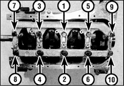
9. Tighten the cover bolts in the sequence shown in the figure with the specified torque of the 1st stage.
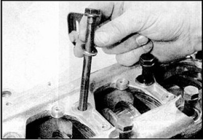
10. Using a torque wrench with a socket head, tighten the bolts of the covers to the specified torque of the 1st stage.
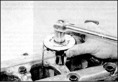
11. Tighten the bolts to the angle corresponding to the 2nd stage of tightening, following the sequence indicated. If a wrench with an angle scale is not available, then tighten the bolts with a torque wrench to the torque specified for the 2nd stage of tightening.
12. Check the freedom of rotation of the crankshaft, then install the remaining parts (see paragraphs. 13–16).
13. Check the cleanliness of the split surfaces of the rear oil seal holder and cylinder block. Make a mark indicating the depth of the gland in the holder, then remove the gland from the holder by prying it out with a large flat blade screwdriver.
14. Install a new oil seal in the holder, making sure that the lips of the working edges are facing the engine. Press in the stuffing box with light blows of a hammer to a depth that corresponds to the mark made before removing the used stuffing box.
15. Check that the drive pins are present, then apply a bead of sealant to the split surface of the gland holder. Put the oil seal holder on the crankshaft and install on the cylinder block. Tighten the mounting bolts to the specified torque.
16. Install the flywheel, camshaft timing chains and oil pan.