


Dismantling
Attention! The engine can be removed from the vehicle as part of the power unit (i.e. assembled with the transmission), then the transmission is separated from the engine for major overhaul.
The power unit is lowered and removed from under the car. In order to freely remove the engine in this way, the car must be raised to a height of at least 75 cm (from the floor to the front bumper) and place on stands.
1. Place the car on a firm, level surface. Block the rear wheels and apply the handbrake. Raise the front of the car and place it on stands in compliance with all safety regulations.
2. Remove the front wheels.
3. Loosen the screws and remove all engine crankcase and mudguard guards.
4. Remove the hood.
5. Drain the coolant into a container (if the liquid is suitable for further use).
6. Drain the oil from the gearbox. Screw in the drain plug and the check/filler plug, tighten both plugs to the specified torque.
7. If the engine is to be disassembled, drain the oil and remove the oil filter if necessary. Clean and tighten the drain plug to the specified torque.
8. Remove the radiator assembly with hoses and fans.
9. Remove the generator and disconnect the wiring from the starter.
10. Remove the power steering pump.
Carburetor engines
11. On carburetor engines, remove or disconnect the following parts and assemblies:
- air filter;
- fuel supply hose and return hose from the fuel pump (plug all openings to prevent fuel loss and dirt ingress);
- throttle cable;
- carburetor wiring connectors;
- brake booster vacuum hose, coolant hose, valve vacuum hoses and crankcase ventilation hoses mounted on the intake manifold;
- intake manifold support bracket;
- exhaust pipe.
12. On vehicles equipped with a catalytic converter, disconnect the connector from the exhaust gas sensor.
Single-nozzle injection engines
13. On single-nozzle injection engines (with preliminary preparation of fuel mixture) remove the air filter.
14. Perform fuel system decompression procedures, disconnect the fuel supply hose and the return fuel hose from the throttle chamber (plug all openings to prevent fuel loss and dirt ingress).
15. Disconnect the throttle cable.
16. Disconnect the wiring connectors from the throttle body, intake manifold and other components.
17. Disconnect the brake booster vacuum hose, coolant hose, valve vacuum hoses, and crankcase ventilation hoses mounted to the intake manifold.
18. Remove the intake manifold support bracket.
19. Remove the exhaust pipe.
Injection engines with direct fuel injection
20. On direct fuel injection engines, perform the following steps: remove the air filter duct.
21. Perform fuel system decompression procedures, disconnect the fuel supply hose and the return fuel hose from the throttle chamber (plug all openings to prevent fuel loss and dirt ingress).
22. Disconnect the throttle cable.
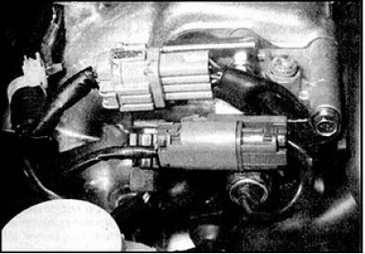
23. Disconnect the wiring connectors from the throttle body, intake manifold, and other components. Move the wiring away from the manifold and cylinder head so that it does not interfere with engine removal.
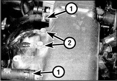
24. Disconnect the brake booster vacuum hose, coolant hose, valve vacuum hoses (1) and crankcase ventilation hoses from the intake manifold (2 - ground bolts).
25. Remove the intake manifold support bracket.
26. Loosen the clamps and disconnect the heater hoses and other cooling system hoses from the engine, after marking the original location of each hose.
27. On vehicles equipped with air conditioning, unscrew the compressor mounting bolts and move the compressor to the side. Tie the compressor to the body so that its weight is not supported by the air conditioning line tubes and hoses. Do not disconnect the air conditioning hoses.
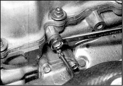
28. Based on the description (see subsection 7.7.4), disconnect all wiring connectors from the ignition distributor, ignition coil and transistor power supply. Release the wiring sleeve from the clamps on the cylinder head and move it to the side. Unbolt and remove all ground wires on the cylinder head and on the intake manifold.
29. Remove the bolts and all ground wires from the cylinder head
30. Remove the axle shafts complete with cardan joints (see subsection 10.2).
31. Disconnect the clutch cable from the gearbox (see subsection 8.3).
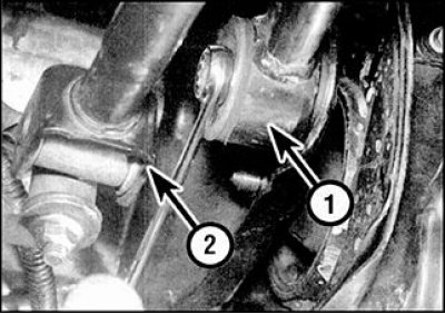
32. Disconnect the gear shift rod (1), gear shift rods (2), speedometer cable and wiring connectors from the gearbox.
33. Bring the hoist hoist and secure it to the cylinder head brackets, tighten the hoist so that it supports the weight of the power unit.
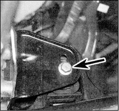
34. Use paint or a marker to mark the location of the tie bolt (indicated by the arrow) on the front support bracket of the power unit, so that during assembly this bolt can be installed in its original position.
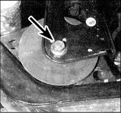
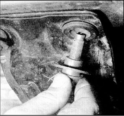
35. Loosen the tightening and unscrew the nut of the clamping bolt (indicated by the arrow), remove the bolt from the support. Unscrew the nut and remove the tie bolt of the rear support of the power unit.
 |
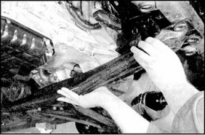 |
36. Unscrew the four bolts securing the central side member, remove the side member, taking it out from under the power unit.
37. Loosen the nut and remove the tie bolt of the right support of the power unit, then loosen the support mounting bolts and remove the support from the engine compartment.
38. If the rubber cushions installed on both sides of the support bracket on the body side are loose, remove the cushions.
39. Unscrew and remove the left powertrain support tie bolt. Then unscrew the three bolts securing the support to the gearbox and move the support to the side. If the rubber cushions installed on both sides of the support bracket are loose, remove the cushions.
40. Once again, make sure that all parts, wires and hoses that may interfere with the removal of the power unit are disconnected or removed. Also make sure that other parts of the car will not be deformed or damaged during the removal of the unit (for example, the traction and control rod of the gearbox).
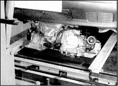
41. If you have a low trolley, roll it under the engine, which will make it easier to remove the removed unit from under the car. Lower the power unit, making sure not to damage or catch nearby parts. It is advisable to perform this operation with an assistant, since you will need to tilt the unit slightly so as not to touch the body panels. Be extremely careful when lowering the engine.
42. Roll the power unit out from under the vehicle.
Removal the gearbox from the engine
1. Secure the removed power unit with wooden blocks, placing it on a workbench or on a clean, level area in the workshop.
2. Loosen the bolts and remove the starter.
3. Make sure the power unit is securely fixed and unscrew the bolts securing the gearbox housing to the engine. Mark the location of the bolts (and on some cars and the corresponding brackets), so that they can be installed in their original places during assembly.
4. Carefully separate the gearbox from the engine, ensuring that the weight of the gearbox is not supported by the input shaft as it exits the clutch driven disc.
5. If the gearbox mounting pins are free to move, remove them and store them for future reinstallation.
Installation
1. If the gearbox was removed from the engine, then perform the operations described below in paragraphs 2–6. If the gearbox was not removed, then perform the installation guided by p. 7 and so on.
2. Apply a thin layer of refractory grease to the splines of the gearbox primary shaft. Excess grease is not allowed, otherwise the friction disc may become oily.
3. Install the pins on the engine or gearbox (if they were filmed), make sure the release bearing is securely mounted on the clutch release fork.
4. Carefully install the gearbox on the engine using the guide pins. When installing, the weight of the gearbox should not be supported by the primary shaft when the shaft enters the splines of the driven clutch disc.
5. Tighten the gearbox housing mounting bolts, making sure that all brackets are installed correctly, and tighten the bolts to the specified torque.
6. Install the starter and tighten the bolts.
7. Place the power unit under the vehicle and attach the engine hoist to the engine brackets.
8. Working with an assistant, lift the power unit into the engine compartment, being careful not to hit any nearby components.
9. Install rubber cushions on the left powertrain support bracket, making sure that the cushion pins enter the bracket holes. Install the support in place, tighten the support mounting bolts to the gearbox and tighten them to the specified torque. Insert the tie bolt and tighten the nut by hand.
10. Install the rubber cushions on the right suspension bracket on the body side, making sure that the cushion pins enter the holes in the bracket. Install the support and tighten the bolts to the specified torque. Insert the tie bolt and tighten the nut by hand.
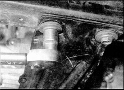
11. Make sure all rubber cushions are in place. Install the limiting ring on the rear support. Install the central side member, tighten the bolts, having previously put washers on them and tighten by hand. Tighten the side member bolts to the specified torque.
12. Insert the rear support pinch bolt and tighten the nut by hand.
13. Insert the front mount pinch bolt. Orient the power unit so that the front mount pinch bolt is precisely aligned with the mark made before disassembly, then tighten the bolt to the specified torque.
14. Rock the power unit back into place, then tighten the front, right and left support tie bolts to the specified torque.
15. Next, install the power unit in reverse order. When installing, make sure that the wiring is laid along the previous routes and secured with clamps and brackets, and that all connectors are connected.
15. Replace the axle shaft seals and install the axle shafts on the gearbox.
16. Connect all cooling system hoses and secure with clamps.
17. Adjust the throttle cable.
18. Connect and adjust the clutch cable (see subsection 8.3).
19. Install and adjust drive belts.
20. Change the oil in the engine and gearbox, recommended oil grades and filling volumes (see subsection 1.12.7).
21. Fill with coolant.
22. When finished, start the engine and check for leaks.