Note. Nominal and maximum permissible values are given in section «Service data and specification» of this chapter.
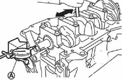
1. Axial clearance of the crankshaft:
Dial indicator (A) measure the gap between the thrust ring and the crankshaft by moving it in the longitudinal direction.
If the measurement results exceed the limit value, replace the thrust rings with new ones and remeasure. If the readings are still abnormal, replace the crankshaft.
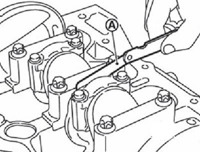
2. Side clearance of connecting rods:
Measure the backlash between the connecting rod and the crankshaft using a set of flat feeler gauges (A).
If the measurement results exceed the limit, replace the connecting rod with a new one and measure again. If the readings are still abnormal, replace the crankshaft.
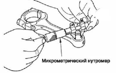
3. Gap between piston pin and piston:
Nutrometer (A) Measure the inner diameter of the bore in the piston.
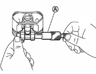
Micrometer (A) measure the outside diameter of the piston pin.
Calculate the clearance between the piston pin and the piston as the difference between the outer and inner diameters.
If the gap exceeds the limit, replace the piston with piston pin assembly.
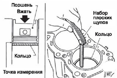
4. Side clearance of piston rings:
Measure the backlash between the piston ring and the groove in the piston using a set of feeler gauges.
If the measurement is out of range, replace the piston ring and remeasure.' If the readings are still abnormal, replace the piston.
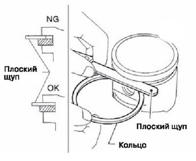
5. Clearance in the lock of the piston ring:
Verify that the bore diameter of the cylinder is correct.
Apply fresh engine oil to the piston (1) and piston ring (2), then push (A) piston ring with the piston up to the middle of the cylinder (IN) and measure the clearance in the piston ring lock using a set of flat feeler gauges (WITH).
If the measurement results exceed the limit value, replace the piston ring with a new one.
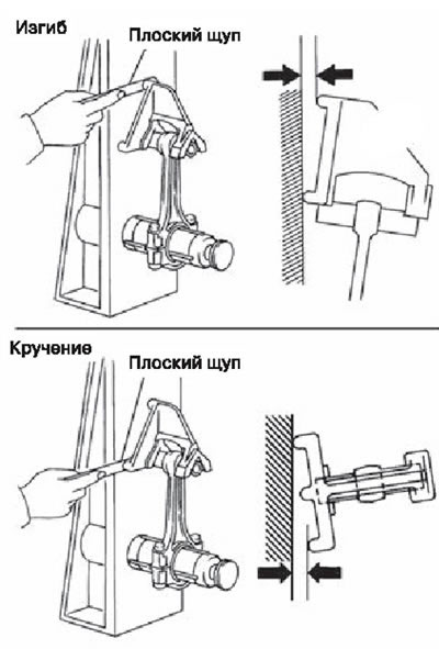
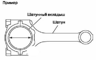
6. Bending and twisting of the connecting rod:
Check the connecting rod using a special stand.
If the maximum values are exceeded, replace the connecting rod with a new one.
7. Connecting rod diameter:
Put the cover on the rod (without inserting inserts) and tighten the connecting rod bolts to the specified torque.
Measure the diameter of the connecting rod bearing bed using an inside gauge.
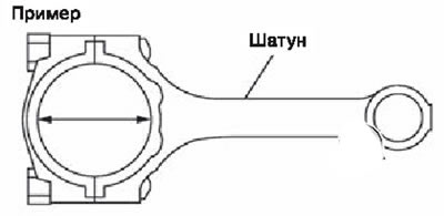
If the size is exceeded, replace the connecting rod with a new one.
8. Clearance in the upper head of the connecting rod:
Measure the inside diameter of the bushing with a micrometer.
Measure the outside diameter of the piston pin with a micrometer.
Calculate the oil clearance at the top end of the connecting rod as the difference between the inside and outside diameters.
If the oil clearance is greater than the limit, replace the connecting rod and/or piston and piston pin. When replacing a piston with a pin, follow the information on the selection of the piston and connecting rod bearings.
9. Block flatness:
Using a scraper, remove the remnants of the gasket from the upper plane of the cylinder block and also clean the surfaces of oil, carbon deposits and other contaminants.
Attention. Be careful not to allow gasket residue to enter the oil and coolant channels in the cylinder block.
Using a straightedge and a flat feeler gauge, measure the distortion of the cylinder block at several points in six directions (1-6).
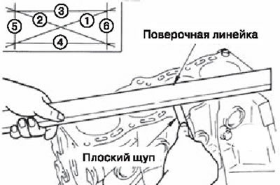
If the measured value is out of specification, replace the cylinder head.
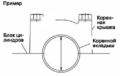
10. Diameter of the bed of the main liners:
- Without installing the main bearings, install the main covers, and then tighten the main bolts to the specified torque.
- Measure the diameter of the crankshaft bed five millimeters from the edge in both directions using an inside gauge.
1. Cylinder block.
2. Main bearing cover
Note. The arrow points to the front of the engine.
If the measured value is out of specification, replace the main cap assembly.
Note. The main bearing caps cannot be replaced separately as they are machined together with the cylinder block.
11. Clearance between piston and cylinder:
Using an inside gauge, measure the wear, ovality, and taper of each cylinder at six points. (In planes "X" And "Y" in sections "A", "IN" And "WITH"), plane ("Y" coincides with the longitudinal axis of the engine).
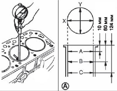
Note. To determine the size group of the cylinder, measure the diameter in the section «IN».
If the dimensional values exceed the maximum allowable or there are scratches and scuffs on the surface, replace the cylinder block with a new one.
Note. Repair dimensions for pistons and cylinder block are missing.
With the help of a micrometer (A) measure the piston skirt diameter.
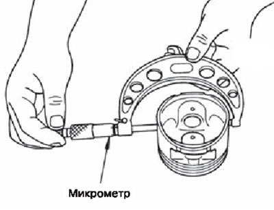
The clearance between the piston and the cylinder is calculated as the difference between the outer diameter of the piston skirt and the inner diameter of the cylinder bore (plane «X» section «IN»).
If the value obtained is out of specification, replace the piston/pin assembly and/or cylinder block.
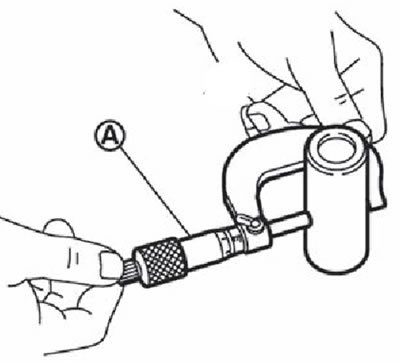
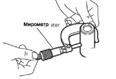
12. The diameter of the crankshaft journals:
Measure the outer diameter of the crankshaft main journal with a micrometer (A).
If the measured value is out of specification, measure the main bearing clearance and if necessary use reduced main bearing shells.
13. Diameter of connecting rod journals:
- Measure the outside diameter of the crankshaft journal with a micrometer.
- If the measured value is incorrect, measure the clearance in the connecting rod bearing and, if necessary, use reduced connecting rod bearings.
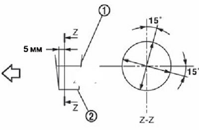
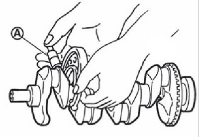
14. Ovality and taper of the crankshaft journals:
Measure the diameter of each main journal and crankpin at four points as shown.
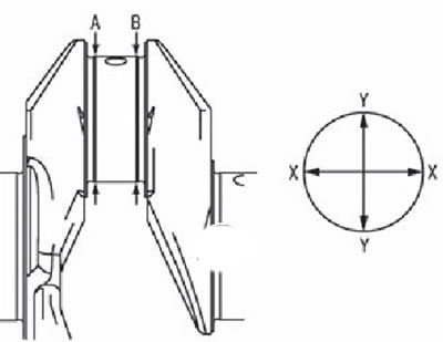
Ovality is determined by the size difference "X" And "Y" at points "A" And "IN".
The taper is determined by the size difference "A" And "IN" about points "X" And "Y".
If the measured values are out of specification, regrind or replace the crankshaft.
After grinding, check the oil clearance on the machined journals. Then pick up the main and / or connecting rod bearings.
15. Runout of the crankshaft:
Install the V-prisms on the marking plate and place the crankshaft on the prisms.
Install dial indicator (A) opposite the middle root neck (№ 3).
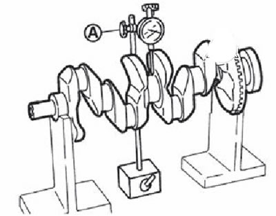
Rotating the crankshaft, measure the runout of the crankshaft along the middle main journal (arrow amplitude).
If the measured value is out of specification, replace the crankshaft.
16. Gap on the crankpin:
A) Estimated clearance definition:
Install the connecting rod bearings in the connecting rod and in the connecting rod cover, tighten the connecting rod bolts to the specified torque.
Measure the diameter of the crankpin bed using a micrometer inside gauge.
Calculate the clearance as the difference between the diameters of the connecting rod bore and the crankpin.
If the obtained value does not meet the specifications, select the connecting rod bearings based on the diameter of the connecting rod bearing bed, the diameter of the connecting rod journal and the required oil clearance.
IN) Gap measurement with a deformable gauge:
Thoroughly clean the connecting rod journal and connecting rod bearings.
Measure and cut a plastic gauge to a length slightly less than the width of the bearing and install axially on the crankpin, not on the oil hole.
Install the connecting rod bearings into the connecting rod and connecting rod cap, and tighten the connecting rod bolts to the specified torque.
Attention. Do not turn the crankshaft.
Remove the connecting rod cap with bearing and read the radial oil clearance using the gauge scale.
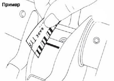
Note. If the gap is greater than the maximum, the measures taken are the same as in the case of the calculation method.
17. Gap on the root neck:
A) Estimated clearance definition:
Install the main bearings in the cylinder block and main covers, install the main covers of the crankshaft bed and tighten the main bolts to the specified torque.
Measure the diameter of the crankshaft bed using an inside gauge.
Calculate the clearance as the difference between the bore diameters of the main bearing and the main journal.
If the obtained value does not meet the specifications, select the main bearings based on the diameter of the bed of the main bearings, the diameter of the main journal and the required oil clearance.
IN) Measuring gaps with a deformable gauge:
Thoroughly wipe the main neck and main bearings.
Measure and cut a plastic gauge to a length slightly less than the width of the bearing and install it axially on the main journal, not on the oil hole.
Install main bearings in cylinder block and main bearing cover, tighten main bolts to specified torque.
Attention. Do not turn the crankshaft.
Remove the main bearing cover with the bushing and read the radial oil clearance on the scale.
Note. If the gap is greater than the maximum, the measures taken are the same as in the case of the calculation method.
18. Protrusion of the main bearing:
After removing the root cap with the liner, which has been tightened to the specified torque, the end of the liner should protrude above the bed connector.
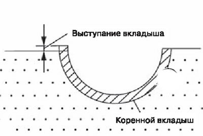
If there is no protrusion, replace the bearings.
19. Protrusion of the connecting rod bearing:
After removing the connecting rod cap with the liner, which has been tightened to the specified torque, the end of the liner should protrude above the bed connector.
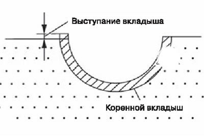
If there is no protrusion, replace the bearings.
20. Main bolt outer diameter:
Measure diameters "d1", "d2"), as it shown on the picture.
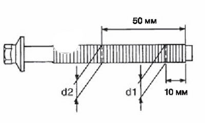
If the bolt thinning appears outside the section «d2», take this value as the diameter "d2". Maximum allowable difference ("d1" - "d2"): 0.2 mm.
If the difference is greater than the limit, replace the main bolt with a new one.
21. Outer diameter of connecting rod bolt:
Measure diameter "d" connecting rod bolt as shown.
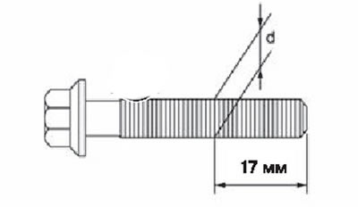
If the bolt thinning appears outside the section "d", consider this diameter as "d". Limit value: 7.75 mm.
If the bolt is thinner than the limit "d", replace it with a new one.
22. Flywheel runout:
Dial indicator (A) measure the runout of the flywheel running surface as shown in the figure.
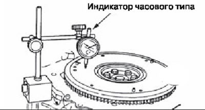
If the measured value is greater than 0.25 mm, replace the flywheel with a new one.