2. Remove the cylinder head.
3. Remove the knock sensor.
Attention. Do not strike the knock sensor.
4. Remove the crankshaft position sensor (POS) with lid.
Attention.
- Do not hit the sensor and avoid hitting it.
- Do not disassemble the sensor.
- Keep the sensor away from metal parts.
- Do not place the sensor in the area of the muted field.
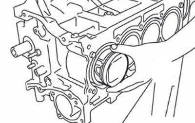
5. Remove the piston with connecting rod assembly as follows:
- Before removing the piston and connecting rod assembly, check the connecting rod backlash on the crankshaft pin.
- Place the crankshaft journal in the position corresponding to the bottom dead point.
- Remove the connecting rod cover.
- Using a hammer handle or similar tool, push the piston and connecting rod assembly toward the cylinder head.
Attention.
- Be careful not to damage the contact surfaces of the connecting rod cap.
- Be careful not to damage the cylinder bore and crankshaft journal with the beating lower end of the connecting rod.
6. Remove connecting rod bearings.
Attention. Mark the installation position of the parts so as not to overdo it during subsequent assembly.
7. Remove the piston rings from the piston using a special expander (A).
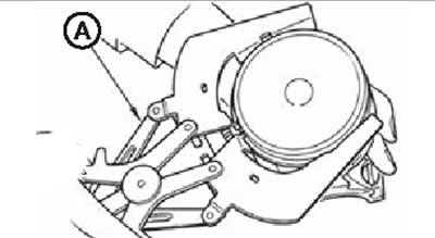
Note. Before removing the piston rings, measure their backlash.
Attention.
- Be careful when removing the piston rings so as not to damage the piston.
- Be careful not to damage the piston rings during their expansion.
8. Remove the piston from the connecting rod:
Using the special tool, remove the piston pin.
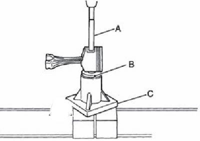
A. Mandrel (KV10109730).
B. Center cup (KV10110310).
C. Foundation of the press (ST13030020).
Attention. Be careful not to damage the piston and connecting rod.
Note. The piston pin is pressed into the upper head of the connecting rod.
9. Remove the main bearing caps as follows:
- Measure the crankshaft end play before loosening the main bearing cap bolts.
- Unscrew the bolts of the main bearing caps in the order shown in the figure, using the TORX socket (E14).
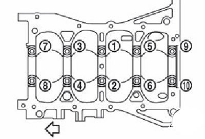
Note. The arrow points to the front of the engine.
Remove the main bearing caps from the cylinder block by tapping them with a plastic mallet.
10. Remove the crankshaft (2).
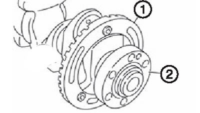
Attention.
- Be careful not to damage or deform the signal plate (1), mounted on the crankshaft.
- If the crankshaft is on a flat floor surface, a wooden topo block must be used to prevent the signal plate from moving across the floor.
- Do not remove the signal plate unless absolutely necessary.
Note. Use the TORX socket to remove and install the signal plate (T40).
11. Remove the rear oil seal from the crankshaft.
12. Remove the liners of the main bearings (upper and lower) and thrust rings from the cylinder block and main bearing caps.
Attention. Apply alignment marks for correct assembly later and store parts without mix-ups.