Valve timing
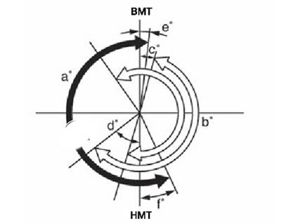
Valve timing diagram (with the intake valve phase shifter on)
Note.
- In parentheses are the values when the phase shifter is turned on.
- The white arrow indicates the phases of the intake valve.
- The black arrow indicates the phases of the exhaust valve.
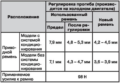
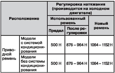
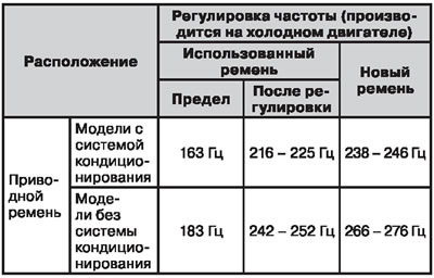
Attachment drive belt
Belt deflection
Belt tension
Belt oscillation frequency
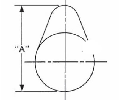
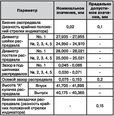
Camshafts and camshaft bearings
 |  |
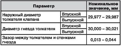
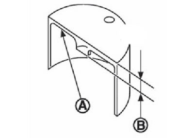
Valve tappets
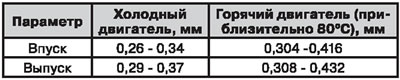
Valve clearances
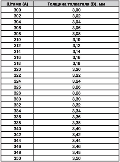
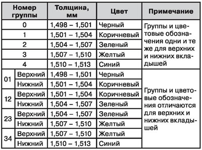
Nomenclature of pusher thicknesses
 |  |
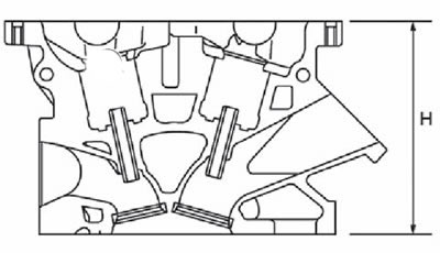
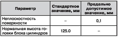
Cylinder head
 |  |
Valve sizes
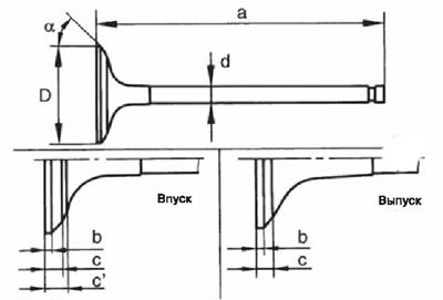 | 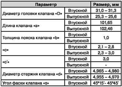 |
Valve guides
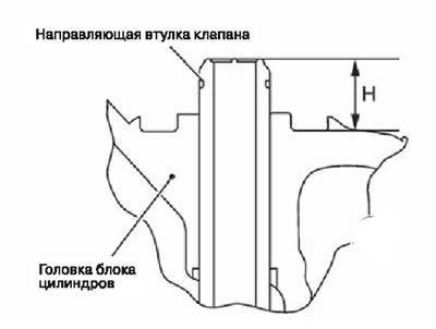 | 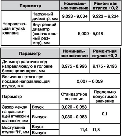 |
Valve seats
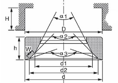 | 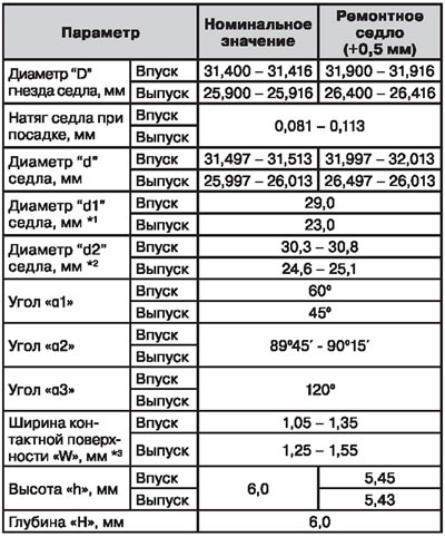 |
Note.
- *1: diameter formed by the boundary of conical parts with angles α1 and α2.
- *2: diameter formed by the border of conical parts with angles α2 and α3.
- *3: mechanical restoration.
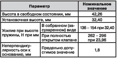
Valve springs
Cylinder block
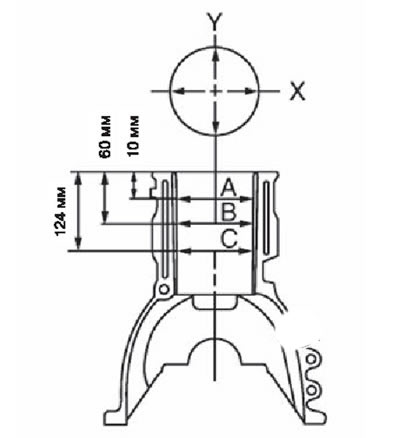 | 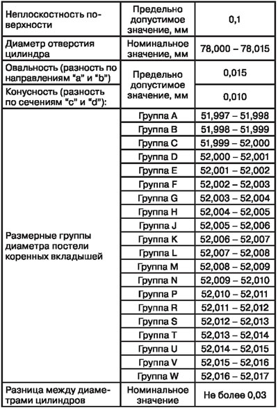 |
Pistons
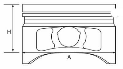 | 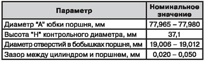 |
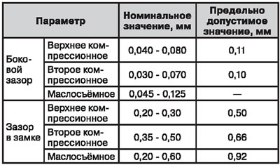
Piston rings
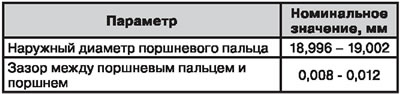
Piston pins
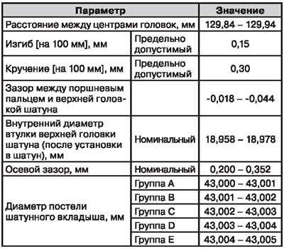
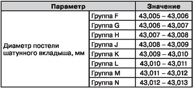
Connecting rods
 |  |
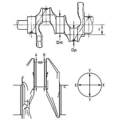
Crankshaft
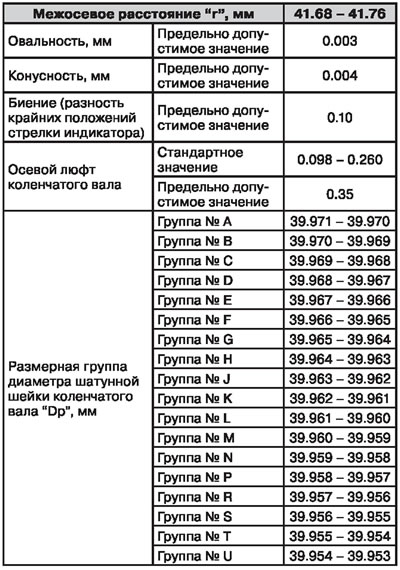 | 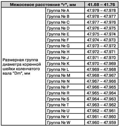 |
Main bearing shells
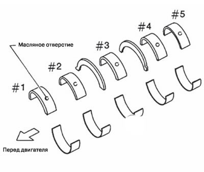 | 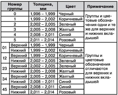 |
Note.
- Repair dimensions of liners: 2.126 - 2.134 mm (+0.25 mm).
- Oil clearance in main bearings: 0.024 - 0.034 mm.
Connecting rod bearings
Note.
- Repair dimensions of liners: 1.627 - 1.635 mm (+0.25 mm).
- Oil clearance in connecting rod bearings: 0.029 - 0.039 mm (maximum allowable: 0.1 mm).