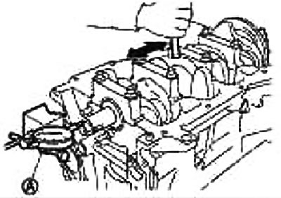
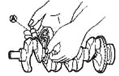
Axial play of the crankshaft
Using the indicator (A) measure the clearance between the thrust bearings and the crank arm by moving the crankshaft back and forth.
Standard: 0.098-0.260mm
Limit: 0.35mm
If the measured value exceeds the limit, replace the thrust bearings and remeasure. If the clearance is still over the limit, replace the crankshaft as well.
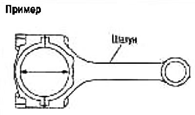
Connecting rod side clearance
With a probe (A) Measure the backlash between the connecting rod and the crank arm.
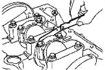
Standard: 0.200-0.352mm
If the measured value exceeds the limit, replace the connecting rod bearings and measure again. If the clearance is still over the limit, replace the crankshaft as well.
Oil clearance between piston and piston pin
Piston pin bore inner diameter
Measure the inside diameter of the piston pin bore using a bore gauge.
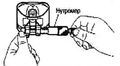
Standard: 19.006-19.012mm
Piston pin outer diameter
Using a micrometer, measure the outside diameter of the piston pin.
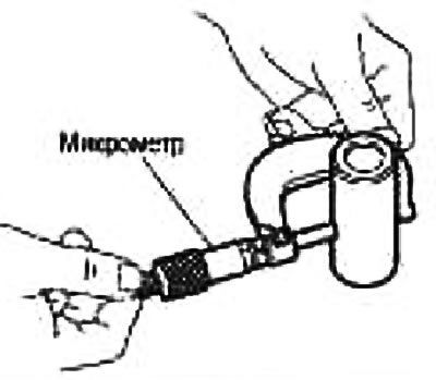
Standard: 18.996-19.002mm
Oil clearance between piston and piston pin
(Piston pin oil clearance) = (piston pin hole diameter) - (piston pin outer diameter)
Standard: 0.008-0.012mm
If the resulting clearance is out of specification, replace the piston and piston pin assembly.
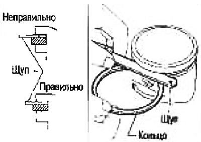
Piston ring side clearance
Use a feeler gauge to measure the clearance between the piston ring and the piston ring groove (see fig.)
| Standard | Top compression | 0.040-0.080 mm |
| Second compression | 0.030-0.070 mm | |
| Oil scraper | 0.030-0.140 mm | |
| limit | Top compression | 0.11 mm |
| Second compression | 0.10 mm |
If the measured value exceeds the limit, replace the piston ring and measure again. If the clearance is still over the limit, replace the piston as well.
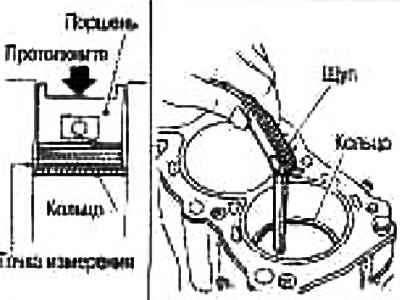
Piston ring gap.
Make sure that the inside diameter of the cylinders is within specification. See below «Clearance between piston and cylinder wall».
Lubricate the piston and piston ring with fresh engine oil and push the piston ring with the piston to the middle of the cylinder and use a feeler gauge to measure the gap in the lock.
| Standard | Top compression | 0.20-0.30 mm |
| Second compression | 0.35-0.50mm | |
| Oil scraper (scraper ring) | 0.20-0.60mm | |
| Limit | Top compression | 0.50 mm |
| Second compression | 0.66 mm | |
| Oil scraper (scraper ring) | 0.92 mm |
If the measured value exceeds the limit, replace the piston ring.
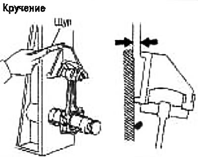
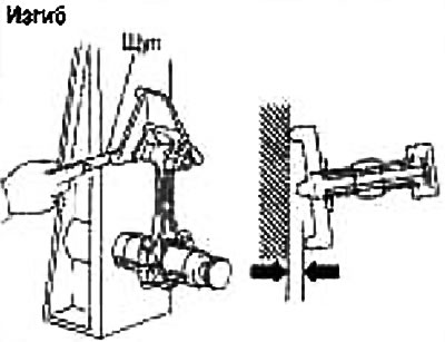
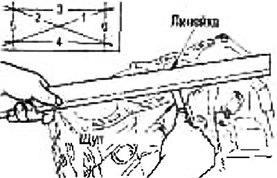
Bending and twisting of the connecting rod
Check with a connecting rod alignment tool.
Ultimate bend: 0.15 mm per 100 mm length
Ultimate torsion: 0.30 mm per 100 mm length
If torsion or bending exceeds the limit, replace the connecting rod assembly.
 |  |
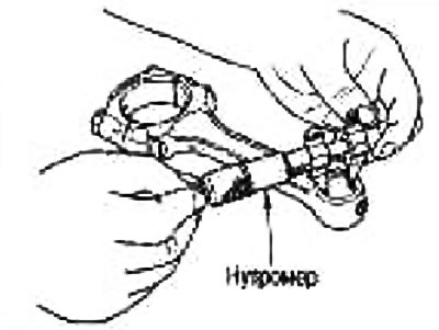
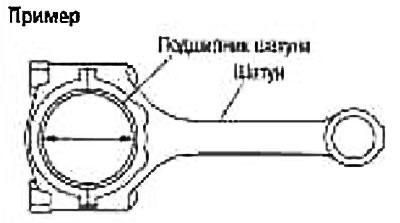
Big end diameter
Install the connecting rod cap without bearing and tighten the connecting rod bolts to the correct torque. For tightening procedure, see «Assembly».
Measure the inside diameter of the big end of the connecting rod with an inside gauge.
Standard: 43.000-43.013 mm
If the inner diameter is out of specification, replace the connecting rod assembly.
Oil clearance bushing small head connecting rod
The inner diameter of the bushing of the small head of the connecting rod
Measure the inside diameter of the connecting rod small end bushing with an inside gauge.
Standard: 10.958-18.970mm
Piston pin outer diameter
Measure the outside diameter of the piston pin with a micrometer.
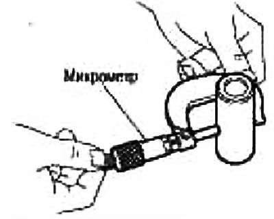
Standard: 18.996-19.002mm
Oil clearance bushing small head connecting rod
(Oil clearance bushing small head connecting rod) = (small end inner diameter) - (piston pin outer diameter)
Standard: -0.018 to -0.044 mm
If the value obtained is out of specification, replace the connecting rod assembly and/or the piston and piston pin assembly.
When replacing the connecting rod assembly, select the connecting rod bearing referring to the section below «Big end bearing oil clearance».
Warping of the cylinder block
Using a scraper, remove any traces of gasket from the surface of the cylinder block, as well as remove oil, scale, carbon deposits and other contaminants.
Caution: Do not allow gasket residue to enter oil or coolant passages.
Check the top surface of the cylinder block for warping by measuring in 6 different directions with a ruler and feeler gauge.
Limit: 0.1mm
If the warpage exceeds the limit, replace the cylinder block.
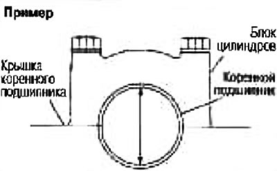
Main bearing housing inner diameter
Install the covers without bearings and tighten the fixing bolts to the required torque. For tightening procedure, see «Assembly».
Using an inside gauge, measure the inside diameter of the main bearing housing.
Take the measurement at the location shown in the figure (5 mm back from the front end of the main bearing housing), in 2 directions. The lower value will be the result of the measurement.
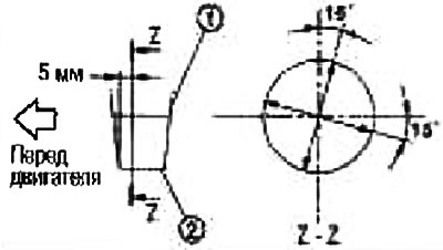
1. Cylinder block
2. Main bearing cap
Standard: 51.997-52.017 mm
If the diameter is out of specification, replace the cylinder block and main bearing caps as an assembly.
Note: The cylinder block and main bearing caps are made in one piece. They can only be replaced as a set.
Clearance between piston and cylinder wall
Cylinder inner diameter
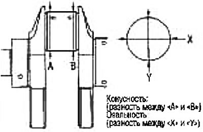
Using a bore gauge, check each cylinder and check for wear, out-of-roundness and taper in 6 different positions: axially «X» And «Y» at points «A», «IN» And «WITH». («Y» - longitudinal axis of the engine).
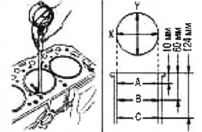
Note: When determining the cylinder diameter class, measure in position «IN».
Standard inner diameter: 78.000-78.015mm
Limit wear: 0.2 mm
ovality (difference between «X» And «Y»): 0.015 mm
Taper (difference between «A» And «WITH»): 0.010 mm
If the measured value exceeds the limit, or if there are scratches and/or scuff marks on the inner walls of the cylinder, replace the cylinder block.
Note: Oversized pistons are not available.
Skirt diameter
Measure the outer diameter of the piston skirt with a micrometer.
measuring point (distance from bottom): 37.1 mm
Standard: 77.955-77.980mm
Clearance between piston and cylinder wall
Perform calculations based on the outer diameter of the piston skirt and the inner diameter of the cylinder (axis «X», dot «IN»)
(Gap) = (cylinder inner diameter) - (outer diameter of the piston skirt)
Standard: 0.020-0.050mm
Limit: 0.09mm
If clearance exceeds limit, replace piston and piston pin assembly and/or cylinder block.
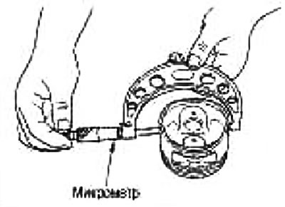
Crankshaft journal diameter
Measure the outside diameter of the crankshaft journals with a micrometer (A).
Standard: 47.959-47.979 mm
If the diameter is out of specification, measure the oil clearance in the main bearings. Then use bearings with a reduced oversize. See below «Oil clearance of main bearings».
Crankshaft journal diameter
Measure the outside diameter of the connecting rod journals with a micrometer.
Standard: 39.953-39.971mm
If the diameter is out of specification, measure the oil clearance in the connecting rod bearings. Then use bearings with a reduced oversize. See below «Oil clearance of connecting rod bearings».
Ovality and taper of the crankshaft journals
Using a micrometer, measure all the main and connecting rod journals at 4 different points as shown in the figure.
Ovality is determined by the difference in size between the axles «X» And «Y» at points «A» And «IN».
The taper is determined by the size difference between the points «A» And «IN» along the axes «X» And «Y».
ovality limit (difference between «X» And «Y»): 0.003mm
Taper limit (difference between «A» And «IN»): 0.004mm
If the measured value exceeds the limit, regrind or replace the crankshaft.
In case of regrinding, measure the oil clearance of the reground main and/or connecting rod journals. Then select the main bearing and/or connecting rod bearing. See below «Oil clearance of main bearings» And «Oil clearance of connecting rod bearings».
Crankshaft runout
Place the prisms on a flat surface and install the crankshaft on them with the outer journals.
Install indicator vertically (A) on the root neck No. 3.
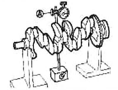
Turning the crankshaft, read the indicator (maximum indicator reading).
Limit: 0.10mm
If the runout exceeds the limit, replace the crankshaft.
Oil clearance of connecting rod bearings
Calculation method
Install the bearings in the connecting rod and cap and tighten the connecting rod bolts to the correct torque. For tightening procedure, see «Assembly».
Using an inside gauge, measure the inside diameter of the connecting rod bearing.
(Oil clearance) = (connecting rod bearing inner diameter) - (outer diameter of the crankpin)
Standard: 0.037-0.047mm
Limit: 0.010mm
If the clearance exceeds the limit, select the required connecting rod bearing according to the diameter of the large end of the connecting rod and the diameter of the crankshaft journal, and achieve the specified oil clearance in the bearing. See section «Connecting rod bearing selection procedure».
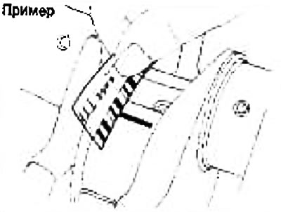
Method using calibrated plastic wire PLASTIGAGE
Completely remove oil and dust from the crankpins and bearing surfaces.
Cut the wire into pieces slightly shorter than the width of the bearings, lay them in the direction of the axis of the crankshaft, but not on the oil holes.
Install the connecting rod bearings into the connecting rods and caps and tighten the bolts to the correct torque. For tightening procedure, see «Assembly».
Attention: Do not rotate the crankshaft.
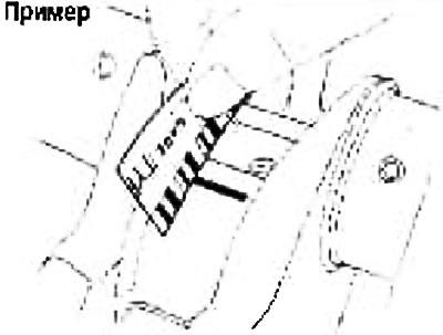
Remove the caps and bearings of the connecting rod and measure the width of the pieces of wire with a scale on its packaging (see fig.).
Note: If the measured value exceeds the limit, take the same measures as indicated in the section below «Calculation method».
Oil clearance of main bearings
Calculation method
Install the main bearings in the cylinder block and covers and tighten the bolts to the required torque. For tightening procedure, see «Assembly».
Measure the inside diameter of the main bearings with an inside gauge.
(Oil clearance) = (main bearing inner diameter) - (crankshaft journal diameter).
Standard: 0.024-0.034mm
If the value obtained exceeds the limit, select the required main bearing according to the inner diameter of the main bearing and the outer diameter of the crankshaft main journal and achieve the specified oil clearance in the bearing. See section «The procedure for selecting main bearings».
Method using calibrated plastic wire PLASTIGAGE
Completely remove oil and dust from the main journals and bearing surfaces.
Cut the wire into pieces slightly shorter than the width of the bearings, lay them in the direction of the axis of the crankshaft, but not on the oil holes.
Install the main bearings in the cylinder block and covers and tighten the bolts to the required torque. For tightening procedure, see «Assembly».
Attention: Do not rotate the crankshaft.
Remove the main bearing caps and bearings and measure the width of the wire pieces with the scale on its packaging.
Note: If the measured value exceeds the limit, take the same measures as indicated in section «Calculation method».
Protrusion of the main bearing above the parting plane
When removing the main bearing caps after tightening to the required torque with the main bearings installed, the edge of the bearing must protrude above the parting plane. For tightening procedure, see «Assembly».
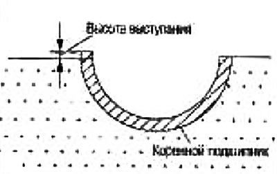
Standard: must have a ledge.
If the main bearings are out of specification, replace them.
Protrusion of the connecting rod bearing above the parting plane
When removing the connecting rod bearing caps after tightening to the required torque with the connecting rod bearings installed, the edge of the bearing must protrude above the parting plane. For tightening procedure, see «Assembly».
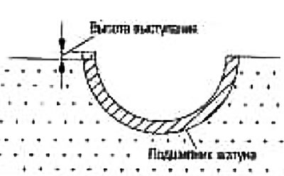
Standard: must have a ledge
If the connecting rod bearings are out of specification, replace them.
Main bearing cap bolt outer diameter
Measure outside diameters («d1», «d2») in the two places shown in the figure.
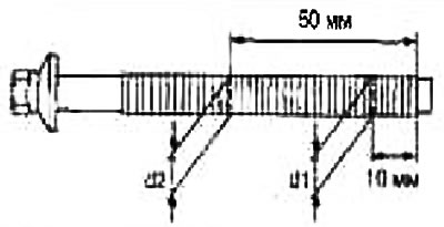
If the narrowing is observed in an area other than «d2», designate it as «d2»
Limit («d1» - «d2») = 0.2 mm
If the narrowing exceeds the limit (big size difference), replace the main bearing cap bolt with a new one.
Outer Diameter of Connecting Rod Bolt
Measure outer diameter «d» at the location shown in the figure.
If the narrowing is observed in a place other than «d», designate it as «d».
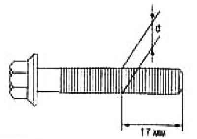
Limit: 7.75mm
When size «d» exceeds the limit (getting thinner), replace the connecting rod bolt with a new one.
Flywheel deformation
Measure the deformation of the contact surface of the flywheel with the clutch using an indicator.
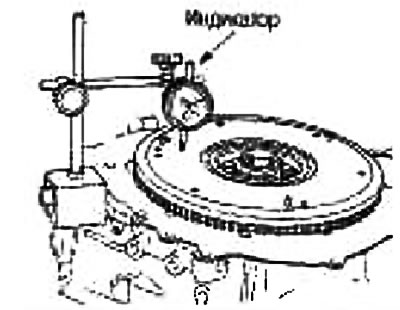
Standard: 0.25mm
If the deformation is abnormal, replace the flywheel.