


Table of contents: Disassembly ↓ Assembly ↓
Disassembly
Note: The following describes disassembly using a stand for an engine with a mount on the gearbox side. If another type of stand is used, please note the difference in the operations, etc.
1. Remove the engine and gearbox assembly from the vehicle and separate the gearbox from the engine. See Section "Engine assembly".
2. Remove the clutch housing and driven disc. See chapter Clutch.
3. Remove the flywheel (on models with manual transmission) or leading disk (on models with automatic transmission).
Secure the flywheel or drive disc (1) with the holder (special tool: KV11105210) (A) and unscrew the mounting bolts.
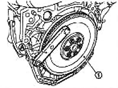
Loosen the mounting bolts using a TORX head (size E20).
Caution: Do not damage or scratch the drive disc (on models with automatic transmission) and the contact surface under the driven clutch disc from the flywheel side.
4. Lift the engine with a winch and install it on the stand.
Caution: Use a stand with sufficient load capacity (about 150 kg or more), which is capable of supporting the weight of the engine.
If the load capacity of the stand is insufficient, remove the following components in advance to reduce the risk of the stand tipping over:
- upper part of the intake manifold; see section "Upper part of the intake manifold";
- exhaust manifold; see section "Exhaust manifold";
- valve cover; see section "Valve cover";
Note: The illustration shows as an example a universal engine stand with a mount on the gearbox side with the flywheel or drive plate removed.
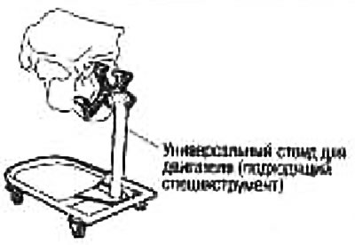
Caution: Before removing the chains, make sure the stand is stable and there is no risk of it tipping over.
5. Drain the engine oil. See chapter Lubrication system and engine cooling system.
6. Drain the engine coolant by removing the plug (1) from the drain hole in the engine.
7. Remove the cylinder head. See section "Removal and installation".
8. Remove the oil pan (upper and lower). See section "Oil pan and coarse oil filter".
9. Remove the knock sensor.
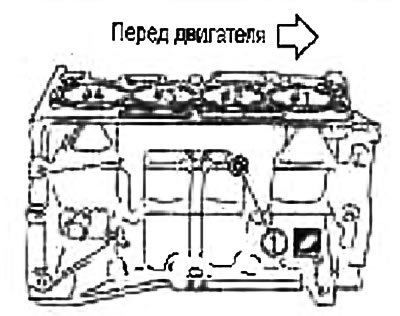
Caution: Handle the sensor with care and avoid impact.
10. Remove the cover and then the crankshaft angle sensor (POS).
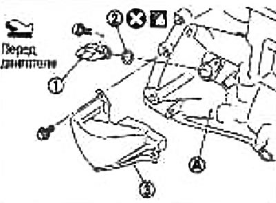
1. Crankshaft angle sensor (POS)
2. O-ring seal
3. Lid
A. Cylinder block on the left side
Attention:
- Handle the delivery device with care, do not drop or hit it.
- Do not disassemble the sensor.
- Avoid allowing metal powder to come into contact with the magnetic portion of the sensor tip.
- Do not leave the sensor in places where it may be exposed to magnetism.
11. Remove the guide bushing (1) using a puller (special tool: ST16610001) (A) or a suitable tool (on models with automatic transmission).
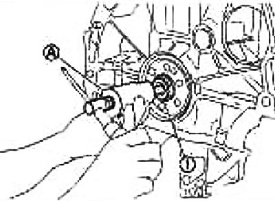
Note: There is no guide bush on models with manual transmission.
12. Remove the connecting rods and pistons as an assembly as follows:
Before removing the connecting rods and pistons as an assembly, check the connecting rod side clearance. See section "Connecting rod side clearance".
- a. Bring the crankpin of the connecting rod being removed to BDC.
- b. Remove the connecting rod big end cap.
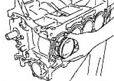
- c. Push the connecting rod and piston assembly toward the cylinder head with a hammer handle or similar tool.
Attention:
- Do not damage the contact surface with the connecting rod bearing cap.
- When removing the large connecting rod head, be careful not to damage the cylinder walls or the connecting rod journal.
13. Remove the bearings from the connecting rod and connecting rod bearing cap.
Note: When removing, mark their installation positions and put them in order without mixing them up.
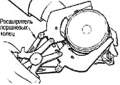
14. Remove the piston rings from the pistons.
Before removing the piston rings, check the piston ring side clearance. See section "Piston ring side clearance".
Use a piston ring expander (suitable special tool).
Caution: When removing piston rings, be careful not to damage the piston. Do not spread the piston rings too wide - they may break.
15. Remove the piston from the connecting rod.
Press out the piston pin using a stand and press.
The following special tool is used:
- Stand: ST13030020
- Punch: KV10109730
- Center Cap: KV10110310
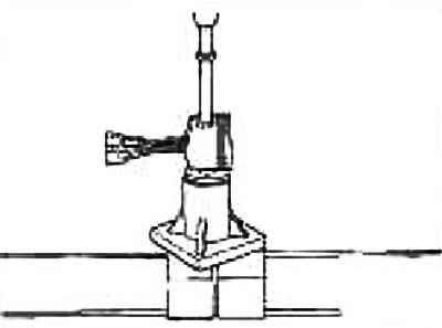
Caution: Do not damage the piston and connecting rod.
Note: The piston pin is press fit into the connecting rod.
16. Remove the main bearing caps as follows:
Before loosening the main bearing cap bolts, measure the crankshaft end play. See section "Crankshaft axial play".
- a. Loosen and remove the bolts in several passes in the reverse order to that shown in the figure.
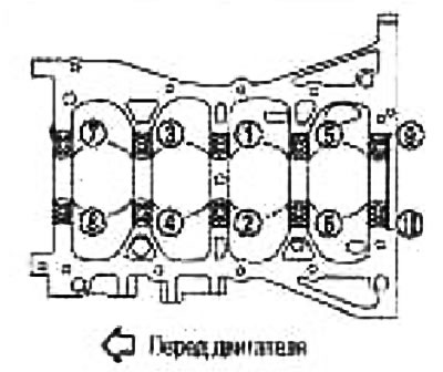
You can use a TORX head (size E14)
- b. Remove the main bearing caps by tapping them lightly with a plastic hammer.
17. Remove the crankshaft (2)
Attention:
- Do not damage or deform the signal disc (1) installed on the crankshaft.
- When placing the crankshaft on the floor, place a wooden block underneath so that the signal disk does not touch the floor surface.
- Remove the signal disc only when necessary.
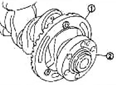
Note: When removing and installing the signal disk, use a TORX head (size: E40).
18. Remove the rear oil seal from the rear end of the crankshaft.
19. Remove the molars (upper and lower) and thrust bearings from the cylinder block and remove the main bearing caps.
Note: When removing, mark their installation positions and put them in order without mixing them up.
Assembly
1. Blow out the coolant passages, oil passages, cylinders and crankcase with compressed air and remove foreign particles from them.
Caution: Wear safety glasses.
2. Screw the plug (1) into the drain hole of the cylinder block as shown in the figure.
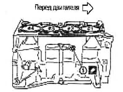
Use brand name sealant or equivalent.
Tightening torque: 9.8 Nm (1.0 kg·m)
3. Install the main and thrust bearings as follows:
- a. Remove dust, dirt and oil from the bearing mating surfaces in the cylinder block and from the main bearing caps.
- b. Install thrust bearings on both sides of journal No.3 (B) in the cylinder block.
Install the thrust bearings with the oil groove (A) towards the crank arm (outward).
- c. Install the main bearings (1), observing the installation direction.
Install main bearings with lubrication holes (A) in the cylinder block, and bearings without them in the main bearing caps.
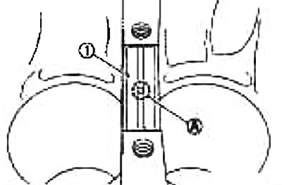
Before installing the main bearings, apply fresh motor oil to the bearing surfaces (from the inside). Do not apply oil to the back side, but wipe it thoroughly.
Make sure the oil holes in the cylinder block are aligned with the holes in the corresponding bearing.
Install the main bearings as shown in the illustration.
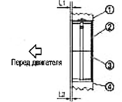
1. Cylinder block
2. Main bearing (upper)
3. Main bearing (lower)
4. Main bearing cap
Note: Install the main bearings in the center, observing the specified dimensions. The center position can be checked visually during repairs.
| Position of the cervix | №1 | №2 | №3 | №4 | №5 |
| L1 | 1.65-2.05 mm | 1.25-1.65 mm | 2.30-2.70 mm | 1.25-1.65 mm | 1.60-2.00 mm |
| L2 | 1.30-1.70 mm | 1.30-1.70 mm | 2.30-2.70 mm | 1.30-1.70 mm | 1.30-1.70 mm |
Note: The dimension "L1" of neck #3 is the distance from the end of the neck body base (jumper) (and not the distance from the end face of the thrust bearing).
4. If the signal disc (1) was removed, install it on the crankshaft.
- a. Install the signal disk (1) on the back side of the crankshaft with the flange facing the counterweight (towards the front of the engine).
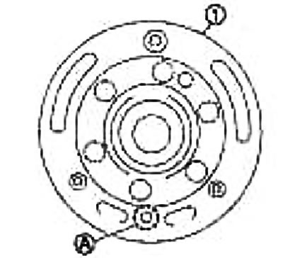
A. Hole for mounting pin.
- b. After installing the crankshaft and signal disk, tighten the bolt using the dowel pin.
Note: Crankshaft alignment pin and signal disc are supplied as a kit.
- c. Remove the locating pin.
Note: Be sure to remove the locating pin.
5. Install the crankshaft into the cylinder block.
Turn the crankshaft by hand and make sure it rotates freely.
Caution: Do not install the rear oil seal yet.
6. Install the main bearing caps.
Use the front mark (B) and the neck number marking (A) as a guide.
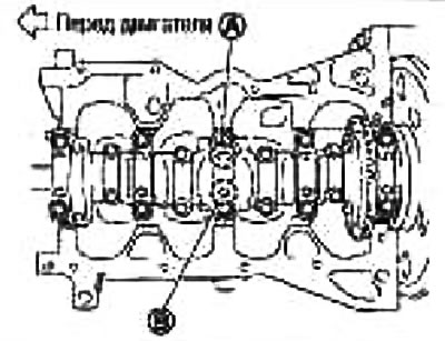
Note: The cylinder block and main bearing caps are manufactured as one piece. They can only be replaced as a set.
7. Tighten the main bearing cap bolts in the order shown by the numbers in the illustration as follows:
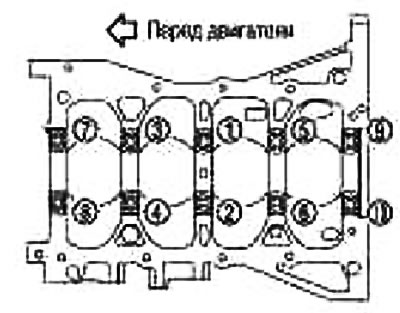
- a. Apply fresh engine oil to the threads and seating surface of the mounting bolts.
- b. Tighten the main bearing cap bolts.
Tightening torque: 32.4 N·m (3.3 kg·m)
- c. Turn 60° clockwise (tightening at an angle) in the order indicated by the numbers in the figure.
Note: Check the tightening angle with a protractor wrench (special tool: KV10112100) (A) Avoid eyeballing without using instruments.
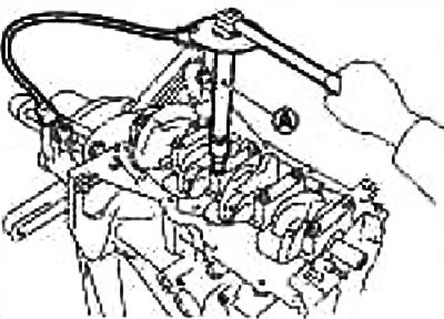
After tightening the mounting bolts, turn the crankshaft by hand and make sure it rotates freely.
Check the crankshaft end play. See the Crankshaft End Play section.
8. Install the connecting rods into the pistons as follows:
- a. Assemble the piston and connecting rod so that the front mark (A) on the piston crown and the cylinder №(C) on the connecting rod are positioned as shown in the figure.
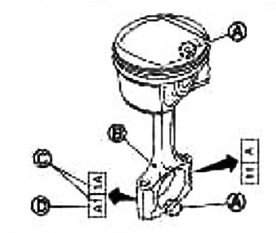
B. Lubrication hole
D. Big End Connecting Rod Class
Note: Symbols without decoding represent a correction code.
- b. Press in the piston pin using a stand (special tool).
The following special tool is used:
- Stand: ST13030020
- Spring: ST13030030
- Punch: KV10109730
- Central shaft: KV10114120
- Center Cap: KV10110310
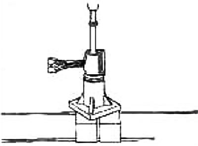
Caution: Press in so as not to damage the piston pin.
Note: The piston pin is press fit into the connecting rod.
Press in the piston pin (2) from the piston side "A" to a depth of 2.35 mm.
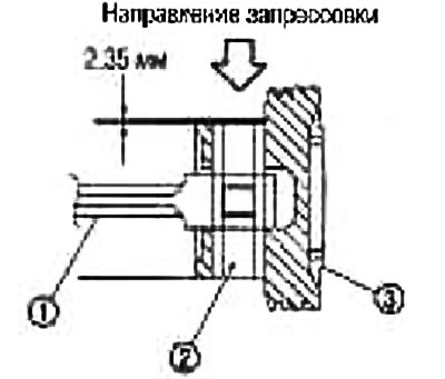
1. Connecting rod
After installation, make sure that the piston (3) moves freely.
9. Install piston rings using a ring expander (suitable special tool).
Attention:
- When installing piston rings, be careful not to damage the piston.
- Do not spread the piston rings too wide - they may break.
Position the piston ring locks relative to the piston front mark (B) as shown in the figure.
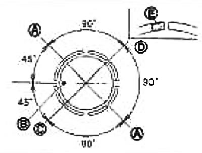
A. Joint of the upper or lower scraper of the oil scraper ring (any of them)
C. Joint of the second compression ring, joint of the oil scraper ring, spacer ring
D. Upper compression ring joint
Place the second compression ring with the stamped marking (E) facing up.
Marking: Second compression ring: "R"
10. Install the bearings into the connecting rods and caps.
When installing connecting rod bearings, apply fresh engine oil to the bearing surfaces (internal). Do not apply oil to the back side, but wipe it thoroughly.
Install the bearing in the center.
Note: There is no stopper projection on the bearing.
Make sure the oil holes in the connecting rod are aligned with the holes in the corresponding bearing.
Install the connecting rods according to the dimensions shown in the figure.
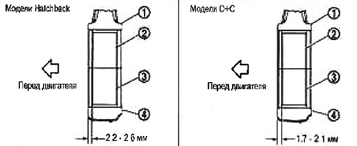
1. Connecting rod
2. Connecting rod bearing (upper)
3. Connecting rod bearing (lower)
4. Connecting rod bearing cap
Note: Install the connecting rod bearing in the center, observing the dimensions shown in the figure. The center position can be checked visually during repair.
11. Install the connecting rods and pistons as an assembly onto the crankshaft.
Bring the crankpin of the connecting rod being installed to BDC.
Apply a generous amount of fresh engine oil to the cylinder walls, piston and connecting rod journal.
Check the cylinder number that the connecting rod corresponds to.
Using a piston ring compressor (special tool: EM0347000Q) (A) or using a suitable tool, insert the piston with the front mark on the piston bottom toward the front of the engine.
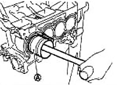
Attention:
- Do not damage the contact surface with the connecting rod bearing cap.
- When inserting the large connecting rod head, be careful not to damage the cylinder walls and the connecting rod journal.
12. Install the connecting rod bearing cap.
Before installation, check that the cylinder number marking (C) stamped on the connecting rod matches the marking on the cover.
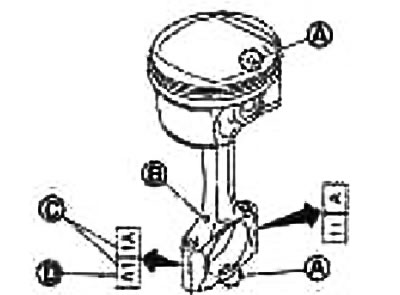
A. Front Mark
B. Lubrication hole
D. Big End Connecting Rod Class
13. Check the outside diameter of the connecting rod bolts. See section "Connecting rod bolt outer diameter".
14. Tighten the connecting rod mounting bolts as follows:
- a. Apply fresh engine oil to the threads and seating surface of the connecting rod bolts.
- b. Tighten the connecting rod bolts.
Tightening torque: 27.5 Nm (2.0 kg·m)
- c. Loosen the bolts completely to 0 Nm (0 kg·m)
- d. Tighten the bolts in several passes.
Tightening torque: 19.6 Nm (2.0 kg·m)
- e. Tighten all bolts 60° clockwise (tightening at an angle)
Caution: Use a protractor key (special tool: KV10112100) (A) Avoid eyeballing without using instruments.
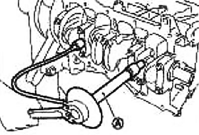
After tightening the bolts, make sure the crankshaft rotates freely.
Check the connecting rod side clearance. See section "Connecting rod side clearance".
15. Install the oil pan (upper). See section "Installation".
Install the rear oil seal after installing the oil pan (upper).
16. Press in the rear oil seal. See section "Installation".
17. Install the flywheel (on models with manual transmission) or leading disk (on models with automatic transmission).
When installing the flywheel (on models with manual transmission) or the leading disk (on models with automatic transmission) on the crankshaft, align the dowel pin on the crankshaft side with the dowel hole on the flywheel/drive plate side.
Install the drive disc (1), reinforcement disc (2) and guide sleeve (3) as shown in the figure (on models with automatic transmission).
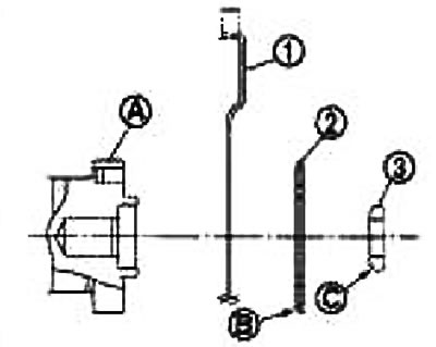
A. Rear end of the crankshaft
B. Rounding
S. Faska
Caution: Observe the installation direction (relative to the front and back).
Using a 33 mm diameter punch, press the guide bushing onto the end of the crankshaft until it stops (on models with automatic transmission).
Tighten the bolts as follows:
- Secure the crankshaft against turning with the crankshaft holder (special tool; KV11105210).
- Tighten the mounting bolts in a crisscross pattern in several passes.
18. Install the knock sensor (1).
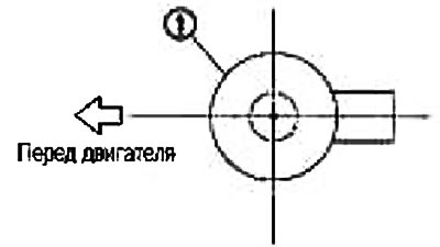
Install the sensor with the connectors facing the rear of the engine.
Attention:
- Do not tighten the bolts by holding the connector.
- If you hit or dropped the knock sensor, replace it with a new one.
Note:
- Make sure there are no foreign particles on the contact surface of the cylinder block and the rear surface of the knock sensor.
- Make sure the knock sensor does not interfere with other parts.
19. Install the crankshaft angle sensor (POS).
Tighten the bolts, making sure the sensor is fully seated in the mounting hole.
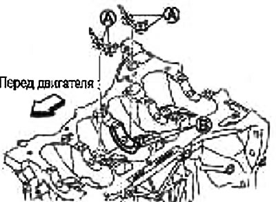
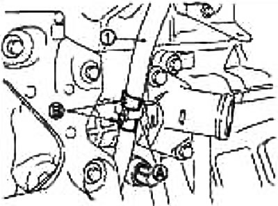
20. When installing the oil dipstick guide (1), secure the section (B) shown in the figure to the inlet manifold (A) by inserting the guide into the side of the cylinder block.
21. After this operation, assembly is performed in the reverse order of disassembly.