Attention:
- When removing a manual transmission from a vehicle, always replace the concentric slave cylinder (CSC). To remove the MCP, the CSC insert is moved to its original position. Dust on the sliding components of the clutch drive plate can damage the CSC seal and cause brake fluid to leak.
- Do not allow grease to come into contact with the surface of the clutch disc, pressure plate and flywheel.
Removing
1. Remove the manual gearbox from the vehicle. See chapter Manual Transmission.
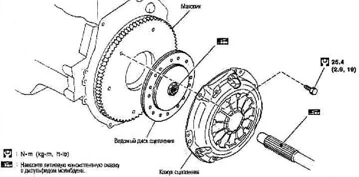
2. Loosen the clutch cover mounting bolts evenly. Remove the clutch cover and clutch disc.
Checking and adjusting after removal (CR engine)
Driven clutch disc
Measure the runout around the perimeter with respect to the center splines of the clutch disc. If it differs from the specified, replace the clutch disc.
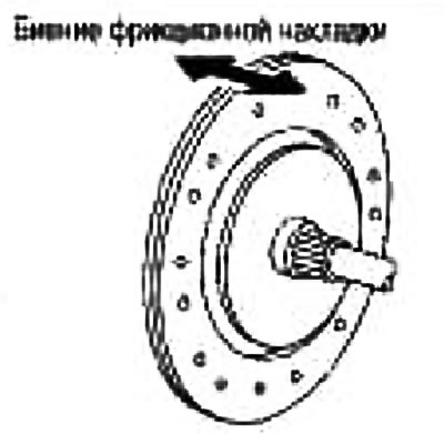
Limit runout / diameter of the measured area:
CR14 Motor: 1.0mm or less/When dia. 180 mm
Motor HR: 1.0mm or less/at dia. 190 mm
Using a caliper, measure the distance from the head of the rivet to the surface of the disc friction lining. If it exceeds the allowable wear, replace the clutch disc.
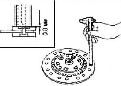
Distance from rivet head to friction lining: 0.3 mm
Clutch cover
Check the unevenness of the tops of the diaphragm spring with the lever inserted. If it is out of specification, adjust the lever height with the aperture wrench (special tool).
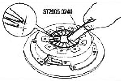
Irregularity of the tops of the diaphragm spring: 0.7 mm
Check for wear or breakage on the thrust ring of the clutch housing. If necessary, replace the clutch cover assembly.
Note:
- A worn thrust ring will make a ticking sound when tapped on the rivet with a hammer.
- A broken thrust ring will make a tinkling sound when the shroud is shaken.
- If any signs of burning or discoloration are found on the contact surface between the pressure plate of the clutch cover and the clutch disc, remove them with emery cloth. If the surface is damaged or deformed, replace the complete component.
Flywheel runout
Using a dial gauge, measure the flywheel runout on the clutch side. If the runout is out of the norm, replace the flywheel. If any traces of burning or discoloration are found on the contact surface, remove them with emery cloth.
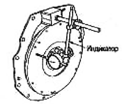
Attention: Take the measurement on the outer surface of the flywheel (where the indicator head is not in contact with the lugs or clutch housing mounting hole).
Installation
1. Clean the driveshaft splines to remove grease and dust.
2. Apply the recommended grease to the clutch disc and drive shaft splines.
Note: The amount of lubricant is 0.4g. The application thickness is 1mm or less.
3. Insert the clutch disc onto the drive shaft. Remove any escaping grease.
Caution: Excessive grease can cause slippage or shaking, and if it comes into contact with the CSC seal, it can cause brake fluid to leak. Wipe off excess lubricant.
Insufficient lubrication can cause knocking, incomplete disengagement, or damage to the clutch.
4. Install the driven disc and clutch cover. Tighten the mounting bolts by hand and install the clutch centering mandrel (special tool).
Special tool number:
A: EM07020000 (CR engine)
A: KV30101000 (HR engine)
5. Tighten the clutch cover mounting bolts evenly in two passes in the sequence shown in the figure.
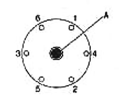
Torque (CR engine):
1st pass: 9.9-19 Nm (1.0-2.0 kg m)
Final pass: 22-29 Nm (2.2-3.0 kg m)
Torque (HR engine):
1st pass: 19 Nm (2.0kg-m)
Final pass: 22-29 Nm (2.2-3.0 kg m)
6. Install the manual gearbox on the vehicle. See chapter Manual Transmission.