


Disassembly
1. Remove the spark plugs using a wrench (suitable special tool).
2. Remove the valve lifters.
Mark the locations and place the components in order without mixing them.
3. Remove the crackers.
Compress the valve spring using a tool, attachment and adapter (special tool: KV10116200) (A) Remove the crackers using a finger magnet (B).
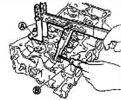
Caution: Be careful not to damage the valve lifter holes when performing this operation.
4. Remove the valve spring retainer and valve spring.
5. Press the valve stem towards the combustion chamber and remove the valve.
Mark the locations and place the components in order without mixing them.
Mark the valves for subsequent assembly.
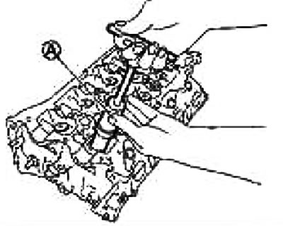
6. Remove the valve seal using a puller (special tool: KV10107902) (A).
7. Remove the valve spring seat.
8. If the valve seat needs to be replaced, see "Replacing the Valve Seat" below.
9. If the valve guide needs to be replaced, see "Replacing the Valve Guide" below.
Assembly
1. If the valve guide was removed, install it. See "Replacing the Valve Guide" below.
2. If the valve seat was removed, install it. See "Replacing the Valve Seat" below.
3. Press in the valve seal.
Press in the valve packing using a gouge (special tool; KV10115600) (A) according to the dimensions shown in the figure.
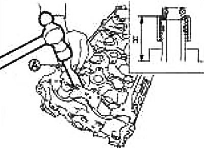
Height "H": 13.2-13.8 mm
4. Install the valve spring seat.
5. Install the valve.
Install larger diameter valves on the intake side.
6. Install the valve spring.
Note: It can be installed in any direction.
7. Install the valve spring retainer.
8. Install the crackers.
Compress the valve spring using a tool, attachment and adapter (special tool: KV10116200) (A) Place the crackers using a finger magnet (B).
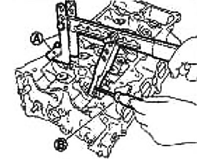
Caution: Be careful not to damage the valve lifter holes when performing this operation.
After installing the valve components, lightly tap the tip of the valve stem with a plastic hammer to ensure proper seating.
9. Install the valve lifter.
10. Screw in the spark plug using the wrench (suitable special tool).
Checking after disassembly
Valve dimensions
Check the dimensions of all valves.
If the dimensions are different from the norm, replace the valve.
Clearance of the guide bushing of the span
Valve stem diameter
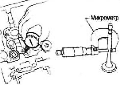
Measure the valve stem diameter with a micrometer.
| Standard | Inlet | 4.965-4.980 mm |
| Release | 4.955-4.970 mm |
Valve guide bushing inner diameter
Measure the inside diameter of the valve guide bushing with a bore gauge.
| Standard | Inlet and outlet | 5,000-5,018 mm |
Valve guide clearance
(Valve guide clearance) = (valve guide inner diameter) - (valve stem diameter)
| Standard | Inlet | 0.020-0.053 mm |
| Release | 0.030-0.063 mm | |
| Limit | Inlet | 0.1 mm |
| Release | 0.1 mm |
If the obtained value exceeds the limit, replace the valve and/or valve guide.
Replacing the valve guide bushing
If the valve guide bushing is removed, replace it with a guide bushing of increased repair size (by 0.2 mm).
1. Remove the valve guide by heating the cylinder head to 110-130°C by immersing it in hot oil.
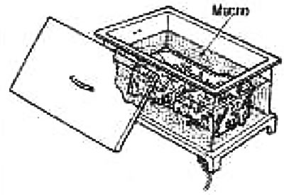
2. Press out the valve guide bushing using a press [with a force of 20 kN (2 tons)] or knock it out using a hammer and punch (suitable special tool).
![2. Press out the valve guide bushing using a press [with a force of 20 kN (2 tons)] or knock it out…](https://www.nissanbook.ru/img/variant/0650.jpg)
Caution: The cylinder head is hot. Wear protective clothing to avoid getting burned while performing work.
3. Ream the valve guide hole in the cylinder head using a reamer (suitable special tool).

Valve guide bore diameter (repair size): Inlet and outlet: 9.175-9.196 mm.
4. Heat the cylinder head to 110-130°C by immersing it in hot oil.

5. Using a punch (suitable special tool) press in the valve guide bushing (1) from the camshaft side, using the dimensions shown.
The article is located on the website [nissanbook.ru]
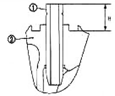
Caution: The cylinder head (2) is hot. Wear protective clothing to avoid getting burned while working.
6. Using a reamer (using special tools) finish the surface of the valve guide bushing.
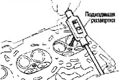
| Standard | Intake and exhaust | 5,000-5,018 mm |
Valve seat contact patch
Perform this check to ensure that the valve guides and valves are within specifications.
Apply red lead (or lead white) on the contact surface of the valve seat and check the fit of the valve to the seat.
Make sure that the red lead imprint appears around the entire circumference without any breaks.
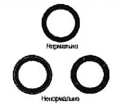
Otherwise, achieve the required degree of valve seating by regrinding it and recheck. If the contact surface is still in poor condition even after rechecking, replace the valve seat.
Replacing the valve seat
If the valve seat is removed, replace it with a valve seat of an increased repair size (by 0.5 mm).
1. Drill out the old seat until it is destroyed. Drilling should not go deeper than the bottom of the seat recess in the cylinder head. For this purpose, install a drilling depth stop on the drill.
Caution: Do not scratch the cylinder head by excessive drilling.
2. Ream the recess in the cylinder head for the valve seat of the repair size.
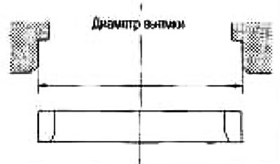
Increased size (by 0.5 mm).
Intake: 31.900-31.916 mm
Issue: 26,400-26,416 mm
Ream in concentric circles toward the center of the valve guide. This will ensure proper seating of the valve seat.
3. Heat the cylinder head to 110-130°C by immersing it in hot oil.
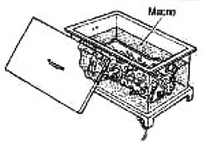
4. Cool the valve seats thoroughly with dry ice. Press the valve seats into the cylinder head.
Attention:
- Do not touch cold saddles with bare hands.
- The cylinder head is hot. Wear protective clothing to avoid getting burned while working.
5. Bring the saddle to the required dimensions by milling or grinding using a suitable special tool.
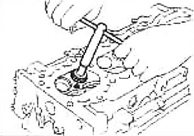
Caution: When milling the surface, grasp the handle with both hands. Then press the milling cutter against the contact surface along the entire circumference and mill in single passes. If the tool is pressed unevenly or with a break, the valve seat may take a stepped shape.
6. Grind the valve using grinding paste.
7. Recheck the valve fit.
Valve spring squareness
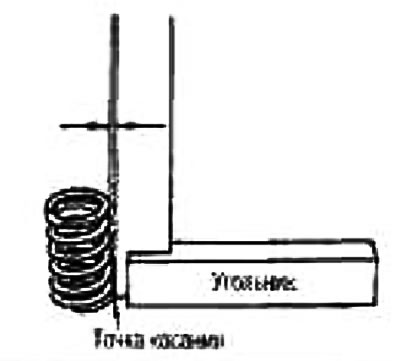
Place a square on the valve spring and rotate the spring. Measure the maximum gap between the top of the spring and the square.
Limit: 1.8 mm
If the clearance exceeds the limit, replace the valve spring.
Valve spring dimensions and compression force
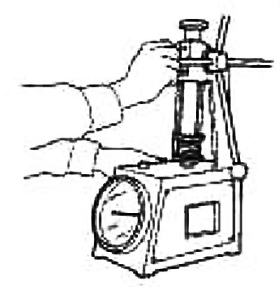
Check the valve spring compression force at standard spring height.
| Standard | |
| Length when unloaded | 42.26 mm |
| Height after installation | 32.40 mm |
| Load after installation | 136-154 N (13.9-15.7 kg) |
| Height with valve open | 23.96 mm |
| Load with valve open | 262-296 H (26.7-30.2 kg) |
If the specified values differ from the norm, replace the valve spring.