


2. Install the safety valve of the lubrication jets.
3. Install the oil jets.
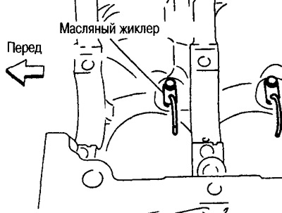
4. Install the main and thrust bearings.
(1) Remove dust, dirt and oil from the bearing mating surfaces in the cylinder block and the main bearing caps.
(2) Install thrust bearings on both sides of cylinder block housing No.3.
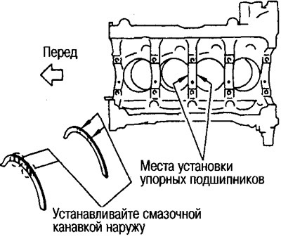
Insert the thrust bearing into the cylinder block with the oil groove facing the crank arm.
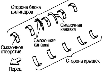
(3) When installing the main bearings, pay attention to the direction.
Install main bearings with lubrication holes and grooves on the cylinder block side, and without lubrication holes and grooves on the cover side.
Before installing the bearings, lubricate the inner surfaces with engine oil. Do not apply oil to the outer sides, but clean them thoroughly.
When installing, align the bearing tabs to prevent rotation.
Make sure that the oil holes in the cylinder block and crankshaft are aligned with the holes in the bearings.
5. Install the crankshaft into the cylinder block.
Turn the crankshaft by hand and make sure it rotates freely.
6. Install the main bearing caps.
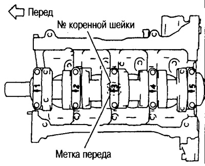
There are markings on the main bearing caps.
Install the caps on the corresponding journals with the front mark facing the front of the engine.
Note: The cylinder block and main bearing caps are manufactured as a single unit and can only be replaced as a set.
7. Check the difference in diameters of the main bearing cap mounting bolts (see section "Main bearing cap bolt diameter difference".
8. Tighten the main bearing cap install bolts in the following order.
(1) Apply engine oil to the threaded areas of the mounting bolts and bolt holes.
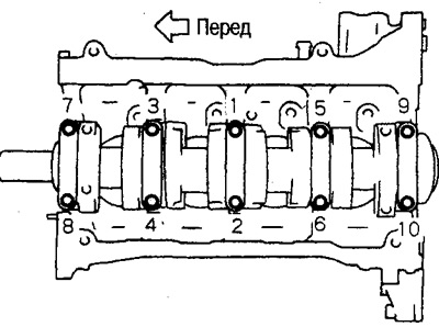
(2) Tighten the mounting bolts in the order shown in the figure to 24.5 - 30.4 Nm (2.5 - 3.1 kg·m).
Note: The cylinder block and main bearing caps are manufactured as a single unit and can only be replaced as a set.
7. Check the difference in diameters of the main bearing cap mounting bolts (see section "Main bearing cap bolt diameter difference".
8. Tighten the main bearing cap install bolts in the following order.
(1) Apply engine oil to the threaded areas of the mounting bolts and bolt holes.
(2) Tighten the mounting bolts in the order shown in the figure to 24.5 - 30.4 Nm (2.5 - 3.1 kg·m).
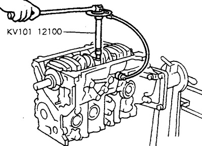
After tightening the main bearing cap bolts, rotate the crankshaft and make sure it rotates freely.
Check the crankshaft side clearance (see section "Crankshaft side clearance").
9. Check the diameters of the connecting rod bolts (see section "Connecting rod bolt outer diameter").
10. Install the pistons onto the connecting rods.
(1) Using snap ring pliers, place the snap ring into the groove on the back of the piston.
Insert the ring firmly into the groove.
(2) Install the piston onto the connecting rod.
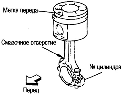
Using a hair dryer or similar device, heat the piston (up to 60-70°C) and insert the piston pin into the piston and connecting rod from the front side of the piston towards the rear side.
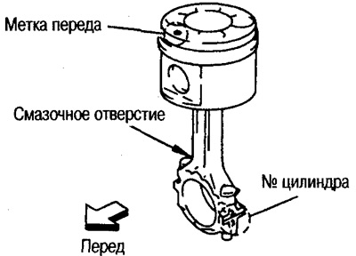
Assemble the piston and connecting rod so that the gear mark on the piston head and the cylinder number mark on the connecting rod are positioned as shown in the figure.
(3) Install the snap ring to the front side of the piston.
See item (1) for installation of snap rings.
After installation, make sure the connecting rod moves freely.
11. Install the piston rings using a piston ring expander.
Caution: Do not damage the piston.
Install the first and second compression rings with the mark facing up.
Tags:
- First compression ring: R
- Second compression ring: 2R
Position the piston ring joints at an angle of 120°.
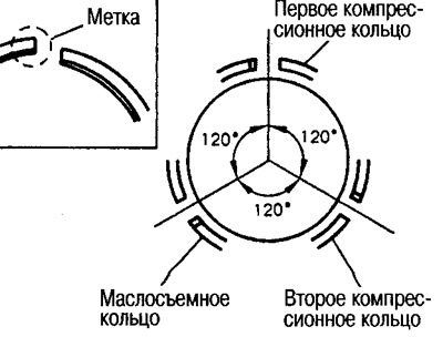
Note: It is sufficient to ensure that the piston ring locks are shifted by 120°.
12. Install the bearings into the caps and connecting rods.
When installing the connecting rod bearings, apply engine oil to the inner surfaces of the bearings. Do not apply oil to the back side, but wipe it thoroughly.
When installing, align the protrusion on the bearing with the recess on the connecting rod.
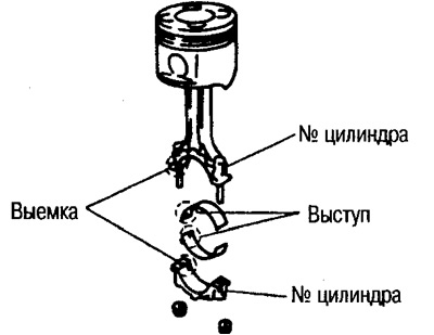
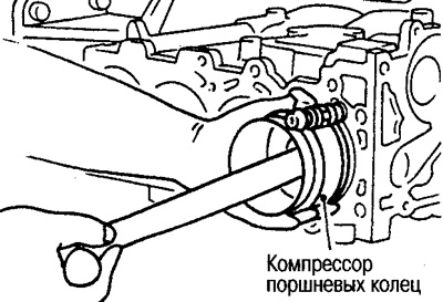
13. Install the piston and connecting rod assembly onto the crankshaft.
Bring the crankpin of the connecting rod being installed to BDC.
Check the connecting rod cylinder number that corresponds to its installation location.
Using a piston ring compressor, insert the piston with the front mark on the piston head toward the front of the engine.
14. Install the connecting rod cover.
Check the connecting rod cylinder number and the cap cylinder number.
Align the front mark on the cover toward the front of the engine.
15. Tighten the connecting rod nuts in the following order.
(1) Apply engine oil to the threads and seating surface of the connecting rod bolts and nuts.
(2) Tighten the nuts to 28.4-30.4 Nm (2.9-3.1 kg·m).
(3) Loosen the nuts completely to 0 Nm.
(4) Tighten the nuts to 18.6-20.6 Nm (1.9-2.1 kg·m).
(5) Tighten the nuts 120-125° (normal 120°).
Caution: Check the tightening angle with a protractor or a protractor. Avoid estimating the tightening angle "by eye" without using tools.
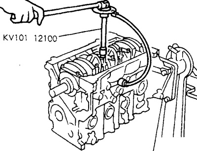
After tightening all bolts, make sure the crankshaft rotates freely.
Check the side clearances of the connecting rods (see section "Checking the connecting rod side clearance").
16. Install the rear oil seal into the rear oil seal holder.
Use a 105mm diameter punch and press the seal to the size shown in the figure.
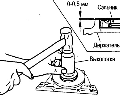
Press in without tilting.
17. Install the rear oil seal holder.
Apply a continuous bead of Three Bond 1207 sealant (KR510 00150) as shown in the figure.
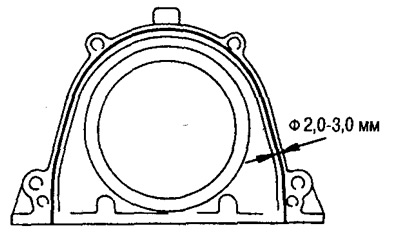
18. Install the guide bushing.
Press in the bushing using a punch with a diameter of approximately 33 mm.
Install the guide bushing with the chamfer facing the crankshaft.
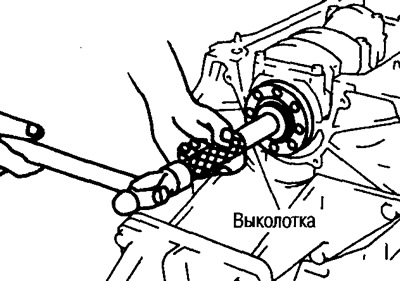
19. Install the fuel injection pump bracket.
Install the insulators according to the shape of the cylinder block together with the brackets and secure.
Align the brackets with the pins on the cylinder block.
The two bolts installed next to the pins are longer than the other two bolts.
Make sure the injection pump pin protrudes the amount shown below.
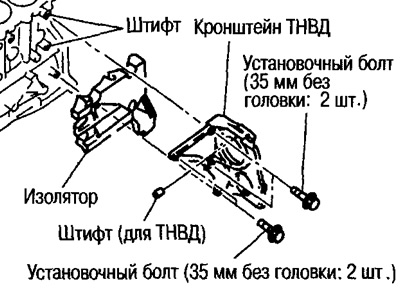
- Standard protrusion: 14.0±1.0 mm
20. Install all parts in the reverse order of disassembly.
Tighten the bracket bolts to the following torques.
A/C Compressor Bracket Bolts:
 : 56.9-65.7 Nm (5.8-6.7 kg·m)
Generator Bracket Bolts:
 : 56.9-65.7 Nm (5.8-6.7 kg·m)
21. Remove the engine from the stand in the reverse order of installation.
22. Install the drive disk.
Install the drive disk and booster disk as shown in the figure.
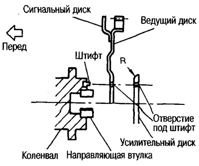
Tighten the mounting bolts, securing the crankshaft with a gear lock (special tool).
Tighten the bolts evenly and diagonally.